
It is already some time ago when I worked together with DonVK and fluid investigating fin horns and especially finding methods how to simulate them properly with BEM. First, off I would like to mention that this collaboration was one of my highlight “diy” experiences. When three people with their respective strengths work together in a concentrated and constructive manner over a longer period of time this is a very good chance creating something special. It all started exploring the original Yuichi/Arai fin horn design and how to simulate it with BEM.
I had started developing my own fin horns already a few years before, but struggled to simulate these horns accordingly. Especially the individual fins or separate channels and their integration as BEM model at throat and at the end of the fins is tricky. You could either simulate them as individual channels but in this case several interfaces are necessary and you could end up with interface issues (one to many and many to one subdomain). Or the BEM model is one single mesh including the fins but then at fin start and end you encounter very close vertices when the fins are very sharp which is a problem with BEM. At that time more questions than answers left for me and these initial designs ended up in the drawer.
Once we solved the major simulation issues for the Yuichi horn we evaluated them and found that they are good but honestly not that good as expected. fluid already started a thread at diyaudio.com here to publish the corresponding results:
Interestingly, some of the current Yuichi issues could be resolved using a different fin arrangement. Such an arrangement was suggested by Kolbrek/Dunker. The outer channels should be in the range of roughly one half of the remaining central channels. In fact the channel width of each channel can be optimized for each horn leaving a huge number of iteration to investigate but stick to one half for the outer channels is very pragmatic and valid approach we used since then. The simple problem is that the different channels are not phase coherent driven by a nearly flat wave front. I have already a solution for this but this will be described in a future article. But the changed fin arrangement is already a significant improvement and worth to be published.
A good occasion to pull my older designs out of the drawer so I suggested to simulate them and compare to Yuichi. But before we go into more detail, wait a minute, what the heck is this strange name mk3b2 about? Well, besides the “fancy” names for some of my previous designs some specify people would say this time I stick with that generic name because it was a simple iteration fine tuning some parameters of my worksheet. Furthermore, is was the iteration that fluid liked most and although our investigation proceeded with other of my fin horn designs fluid constantly compared nearly everything new to the mk3b2. And to our all surprise we thought that the mk3b2 performs better than the Yuichi. Without the help from DonVK and fluid this horn would have never come up to a ready and BEM proven design. Thank you again for our collaboration! I will therefore publish the results and allow the design to be used for free for private use (commercial use is not granted!).
But first let me show again the simulation results using these mk3b2 coordinates:
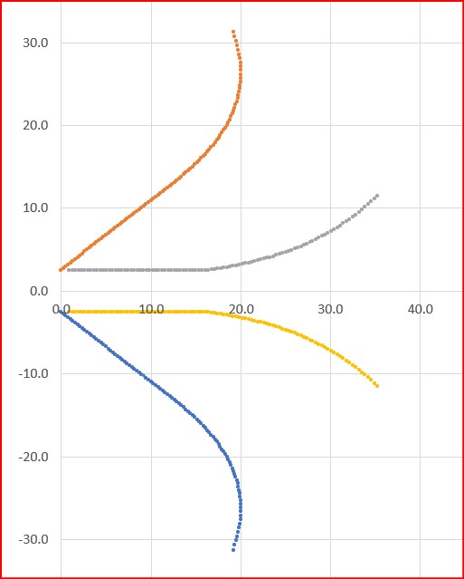
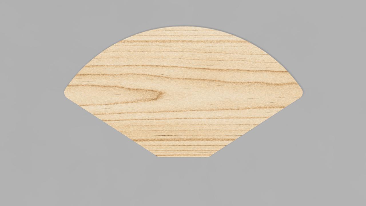
mk3b2 fin horn 2D profile
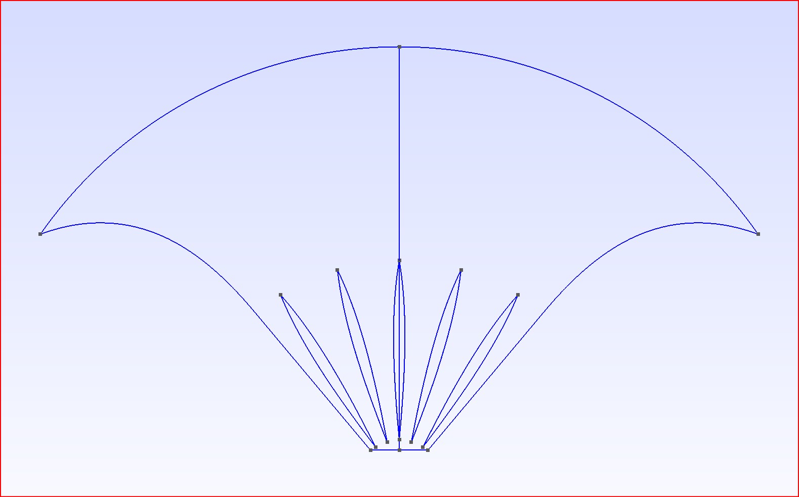
Note that the outer horn walls can be a half fin but do not need to be a half fin. The straight side walls are better and more consistent imo. I will not show how the fins are calculated but I simply distribute material where it is needed on the arc of the construction wave front to provide the correct loading given as parameter which was hyperbolic T=0.7 and 325Hz cut-off. Here is a sketch with the final fin orientation used for mk3b2:
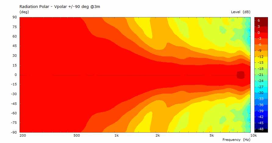
The resulting simulated radiation impedance proves that the approach is working properly:
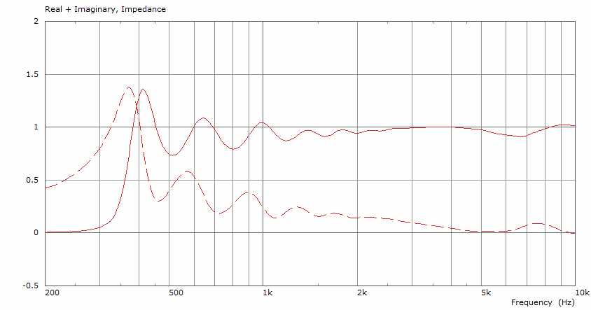
Radiation Impedance of mk3b2 fin horn
It should be stated that we had to keep the number of elements within a reasonable range to be able to simulate these horns with the given computer resources. So don’t expect perfectly smooth curves. And again it should be noted that by adding additional round overs in a readily designed CAD horn the results will even be better, especially for the vertical properties.
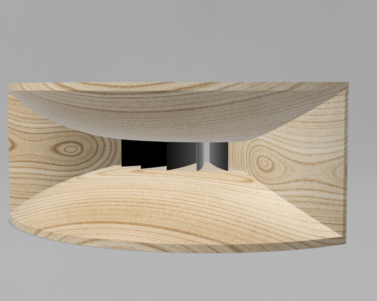
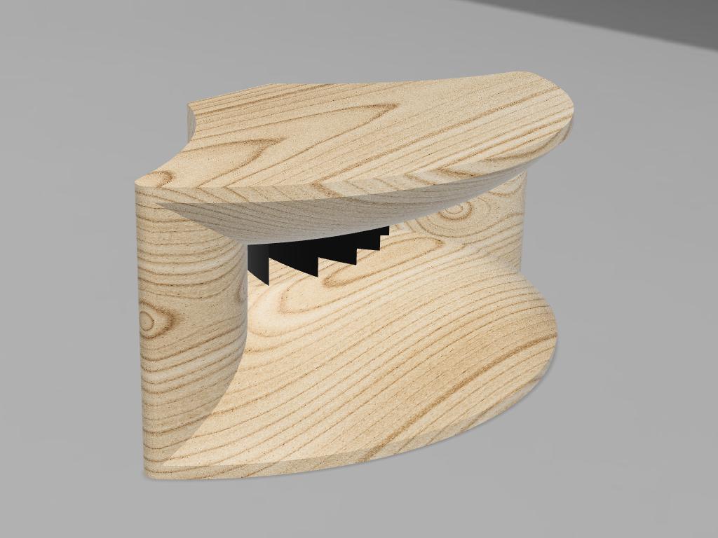
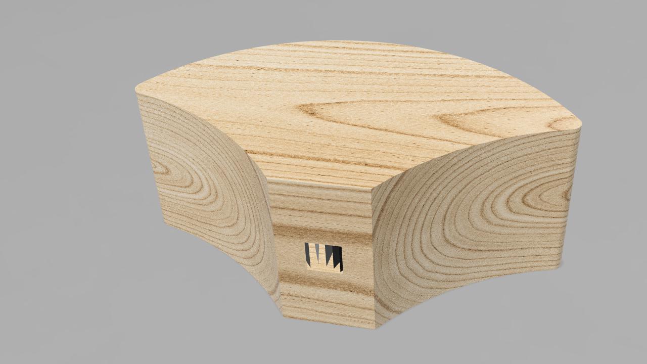
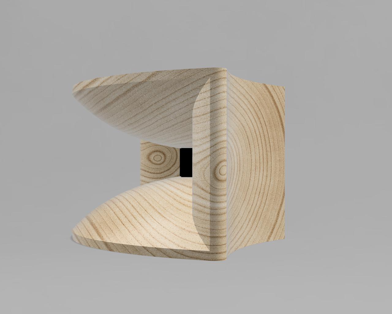
For the download package I will provide the step file for the inner horn profile including the fins. Based on this many different designs are possible. Anyway, I have create two variants which mainly differ with respect to the outer shape of the side walls:
And finally, here are the downloads with horn and adapter CAD files (commercial use not allowed!):
Enjoy! The only missing link is the adapter and how to mount it to the throat section of the horn. I suggest to make an exponential adapter with T=0.7 and 325 Hz cut-off.