
Already during the collaboration with @DonVK and @fluid regarding fin horns, I shared some initial drafts of a radial fin horn with almost equal fin path lengths with help of the semicubic parabola. Traditional fin horns have the shortcoming that the path length from outer throat to find end is shorter compared to the center path length because of the radial fin arrangement. I think that it is very important that the wave front beyond the fins sum up coherently or, so to speak, have the same phase. The mk3b2 horn tried to mitigate the issues with respect to different path lengths by a different fin arrangement, with the result that mk3b2′ performance surpass the current available fin horn designs.
Luckily, one of my other interest at that time was to investigate the Bézier algorithm and how to use it in designing horns (Bezier Curve). The result was a complete horn calculator based on Bézier curves. Besides the challenge to implement the math, I learned how to handle the algorithm and also found out that multiple Bézier points with the same coordinates can be used to emphasize certain regions, where the resulting curve should be more close to a distinct point.
In this article I will describe a new algorithm that starts with a slightly curved wave front which is the result of an optimization to fulfill the defined flare rate. So the first incremental step is more or less the same as a general exponential horn. Bézier curves are used to make the fin path lengths equal, ending up with a spherical wave front at fin end which is the theoretical optimum to radiate into a flared conical bell.
But wait, what is the problem with traditional fin horns? Well, they have a radial blueprint with a point of origin and the fin starts are arranged radially based on the origin. This is only perfect if the sound source is a point source starting at the point of origin, but as soon as the horn sides are separated to build a true throat diameter driven by an almost flat wave front, then it becomes apparent that the central path length from throat to fin end is longer than at the side walls from throat to fin end. So what to do now? The paths of the channels near to the sides need to be made longer to get a coherent wave front at fin exit, but we still want each channel to preserve the fractional exit angle based on the radial blueprint.
Designing phase plugs is quite similar to what has been described, and several publications can be found suggesting different solutions. But a complete fin horn is still a little bit different to a phase plug, and to have an idea does not mean to immediately get out a readily usable design. The main challenges to implement the math was solved already about two years ago, but I was not completely satisfied with the numerical results. There were still some inconsistencies in the code to get all fin paths touching each other perfectly at fin end. To optimize a set of Bézier curves that have the same path length is a quite easy task, but I always want to follow the surface area expansion of each channel to match perfectly to the defined flare rate. It should again be emphasized that the main reason to implement fins is to preserve exponential loading for wide opening horns. Of course, the fins also help to improve the horizontal dispersion for higher frequencies, but this is more or less a side effect.
Some months ago I found the time to debug my old code, and also programmed some refinements so that I am now really satisfied with the results. How to make a path length for a fin channel longer than a straight line can be accomplished in different ways. One possibility is to divide up each channel vertically and let one half go up and the other down, rejoining them before the fin end, or let the complete channel move up or down. A suggestion from the literature was to use some kind of wavy path (moving up and down along the path like a sine wave), but I don’t like this idea because who can be sure that all frequencies follow exactly this groovy structure. The simplest way is to add a curve to the sides. But just after the first initial tests, it became apparent that it is not possible to start with a flat wave front because the defined flare rate would correct this with the second incremental step because of the loading constraint. The only way to preserve loading and get a smooth profile is to define a first short conical section and to optimize the opening angle of this short conical stub based on the defined flare rate. In order to reduce complexity, my approach limit dimensions to 2D. This should be a valid simplification, as the fin height has been kept constant.
For the mathematical implementation, six grid construction points are used with up to 12 Bézier points, so some construction points could be used multiple times with the same coordinates. An even distribution uses 2 Bézier points for each of the six grid point, but other point distributions are possible. The first two construction points define the start conical stub element. The length of this start element is variable but should be kept as short as possible but as long to prevent the channel’s width coordinates to become negative. When the length of the base conical element is defined, its opening angle is optimized to fulfil the pre-defined flare. The next two points are used to optimize the length of the channels, but their start arrangement is exactly along the desired opening angle of the fractional opening angle of the channel’s conical blueprint, like a traditional fin horn. They will simply be rotated in or out with respect to the point of origin. It is possible to let one point rotate clockwise and the other counterclockwise. The last two points are pre-defined somewhere on the conical line of the channel, but they are fixed during the optimization so that everything ends at the desired exit angle:

Construction grid point arrangement at start
After the optimization is done, the two optimization points have moved to the sides. It should be mentioned that the Excel based visualization is not the resulting channel path, as here the line goes through all points like a spline:

Construction grid points after optimization
As the construction points get overlaid with Bézier points, the resulting channel paths look like this. The lines represent the middle of each channel:

Bezier optimized channel paths
Based on the defined flare rate, we get the channel width at each point along the center line and all different channels end up perfectly at fin end while preserving the correct surface area expansion exactly at each point on the trajectory:

Bezier optimized fin channels with a resulting spherical wave front
And this is the result when no optimization is done. The path length difference inner / outer channels is only about 6mm. It may still work sufficiently good.

Bezier fin channels without optimization
But how does this arrangement behave with respect to the goal to get a coherent wave front inside the channels and especially at fin end? To answer this question, I prepared my calculator to put out all necessary stuff for an import to AKABAK and did some BEM verifications. I was only interested to visualize the fields inside the channels and played around with wall impedance at fin end to be able to assess the results. The design goal is that for all frequencies within the pass band of the horn, there should occur an almost perfect summing of the wave fronts at fin exit and reasonable nice looking fields inside the channels. Finally, here are the results for a horn with cut-off of 270Hz and T=0.7 from 250Hz to 20kHz.

250Hz

500Hz

1kHz
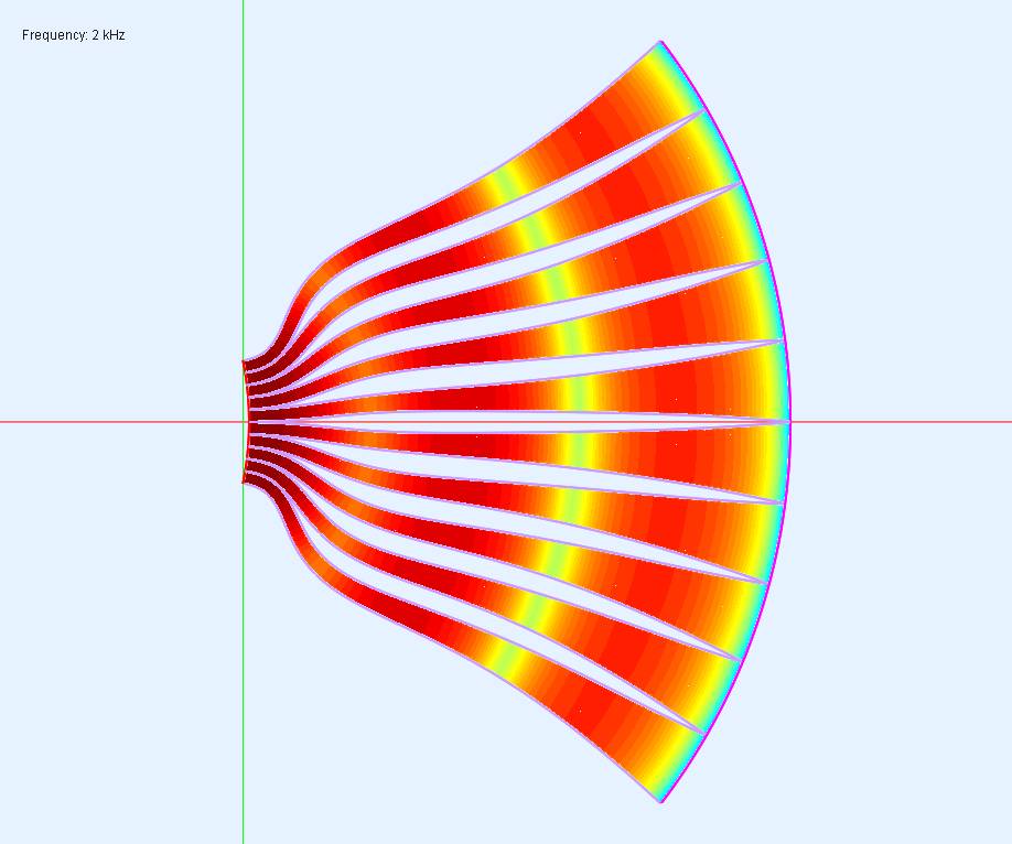
2kHz

5kHz

10kHz

20kHz
Well, I am entirely satisfied with the results 😉
I already have also programmed the second missing link, the flared conical bell, as a separate calculator which needs the fin length and opening angle and throat diameter as input. So the plan is to join the fin part and the conical bell to get the desired fin horn.

Flared conical bell

Flared conical bell
I am quite confident that this design will be the new reference for category of fins horns. The third part is to make an appropriate adapter, which is intended to produce the curved wave front that is assumed initially for this fin horn by setting cut-off, flare rate and throat diameter.

Wave front shaping adapter
Of course, everything is a compromise and the base assumption that the entry wave front is exactly the same as assumed by optimizing the opening angle with the pre-defined flare rate may not perfectly fit the bill. But it should be very close as I have simulated the non optimized fin arrangement, and it still looks quite nicely. Overall, it should be a big improvement compared to the traditional blueprint for fin horns.
Maybe this will be a nice project to actually make such a fin horn in the future…