
Encouraged by the excellent simulation results of my William Neile ALO horns the next logical step was to have a prototype made. But is not so easy to find someone who is willing to spend the time and invest some money / material to produce a prototype. Luckily, I got a hint to contact member pelanj at diyaudio.com forum. Believe me that I remember very well one of his first words: “I am excited and honored to be a part of it.” This indeed was the kick-off of our collaboration. It was a pleasure to work with him so far so that I am now able to proudly present the first prototype based on my own horn design made by Jaroslav. If any desire should arise to purchase one of my William Neile horns, then Jaroslav is the only person so far who is allowed to make them in Europe. At this point I would like to emphasize again that I do not charge any license fees or receive any other profit sharing. Any cost calculation is not at my discretion.
I would also like to express my thanks to DonVk and fluid for the valuable discussions and suggestions and help with CAD software on the way to the first prototype.
A very special thanks goes to Roland (Ro808), who was indeed the first to recognize the potential of my work and contacted me through a forum some years ago and played a not inconsiderable part that I am running this blog.
The main goal for this project milestone was to create a cost-effective prototype, i.e. compromises can certainly be made in terms of optics. The simulations should primarily be supported by real measurements. This is commonly referred to as a proof of concept. So please don’t be bothered by the maybe not perfect optics / finish. The material Jaroslav used for the prototype was also chosen to be cost effective and not optimal for his workflow which caused a lot of work after milling. I am convinced that the finish of later horns will be beyond any doubt.
To make a long story short, this is what I received some weeks ago and I was very excited when the first William Neile ALO horn lay on the table in front of me. What a satisfaction after all the theoretical work. I proudly present the 1in0 prototype:
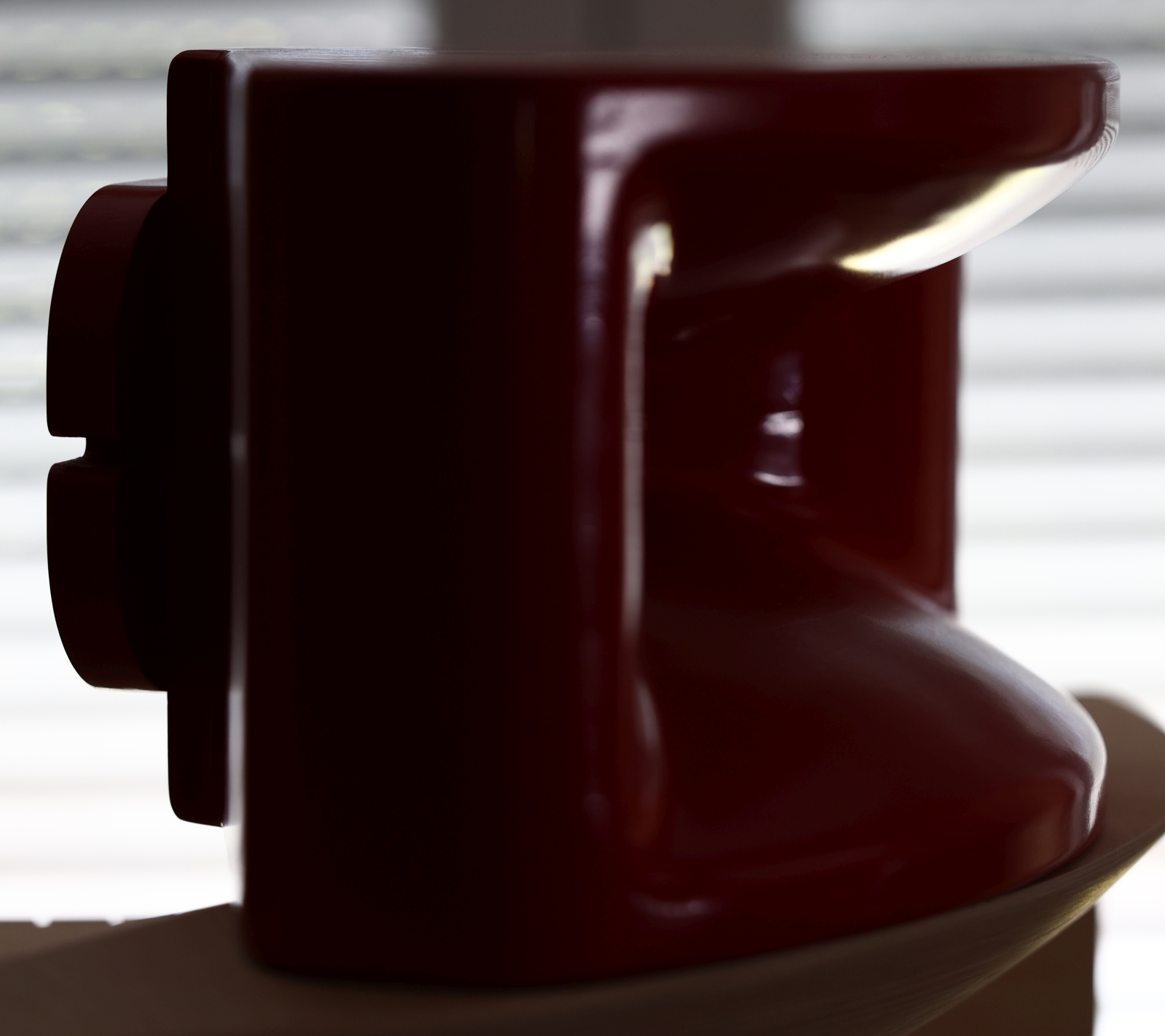
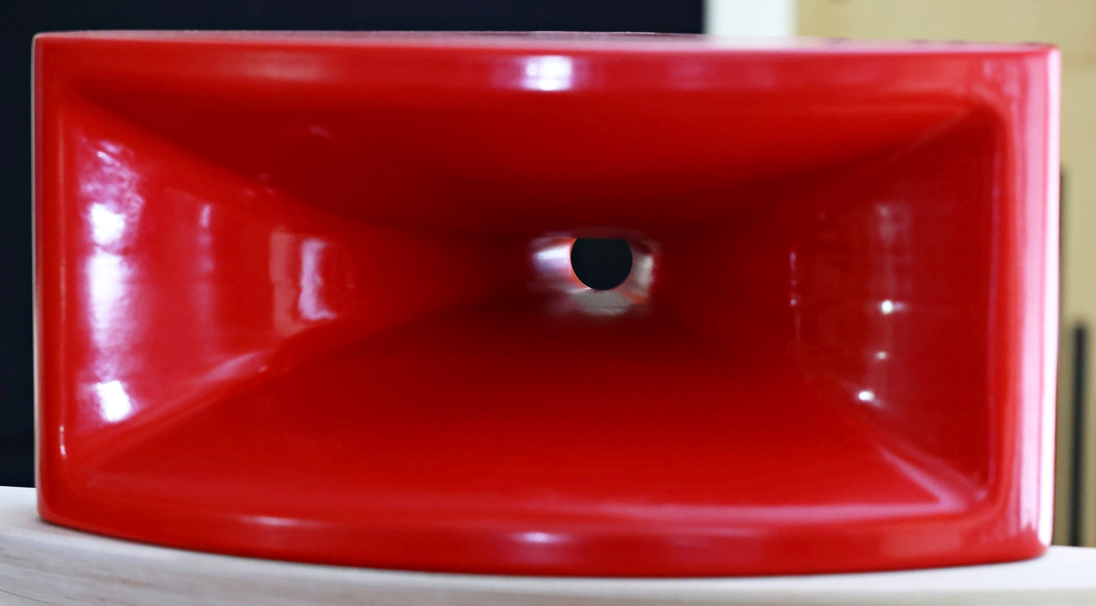
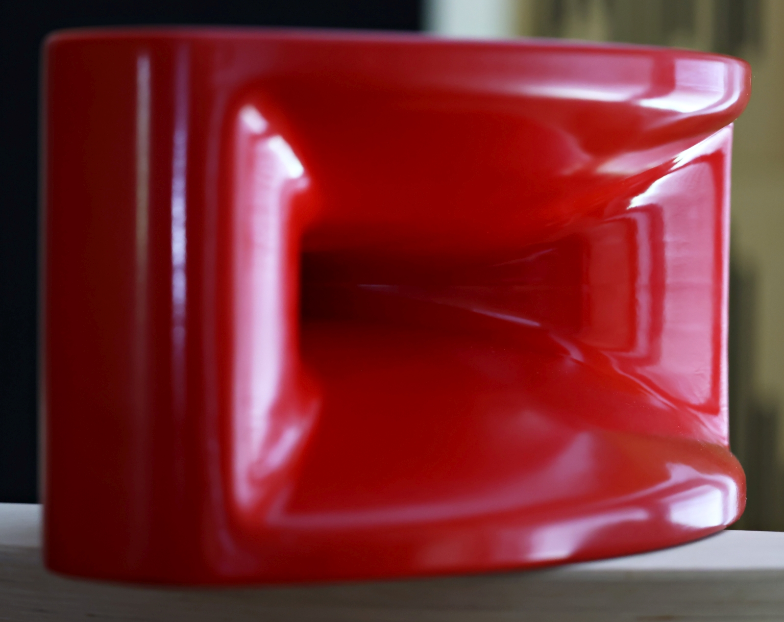
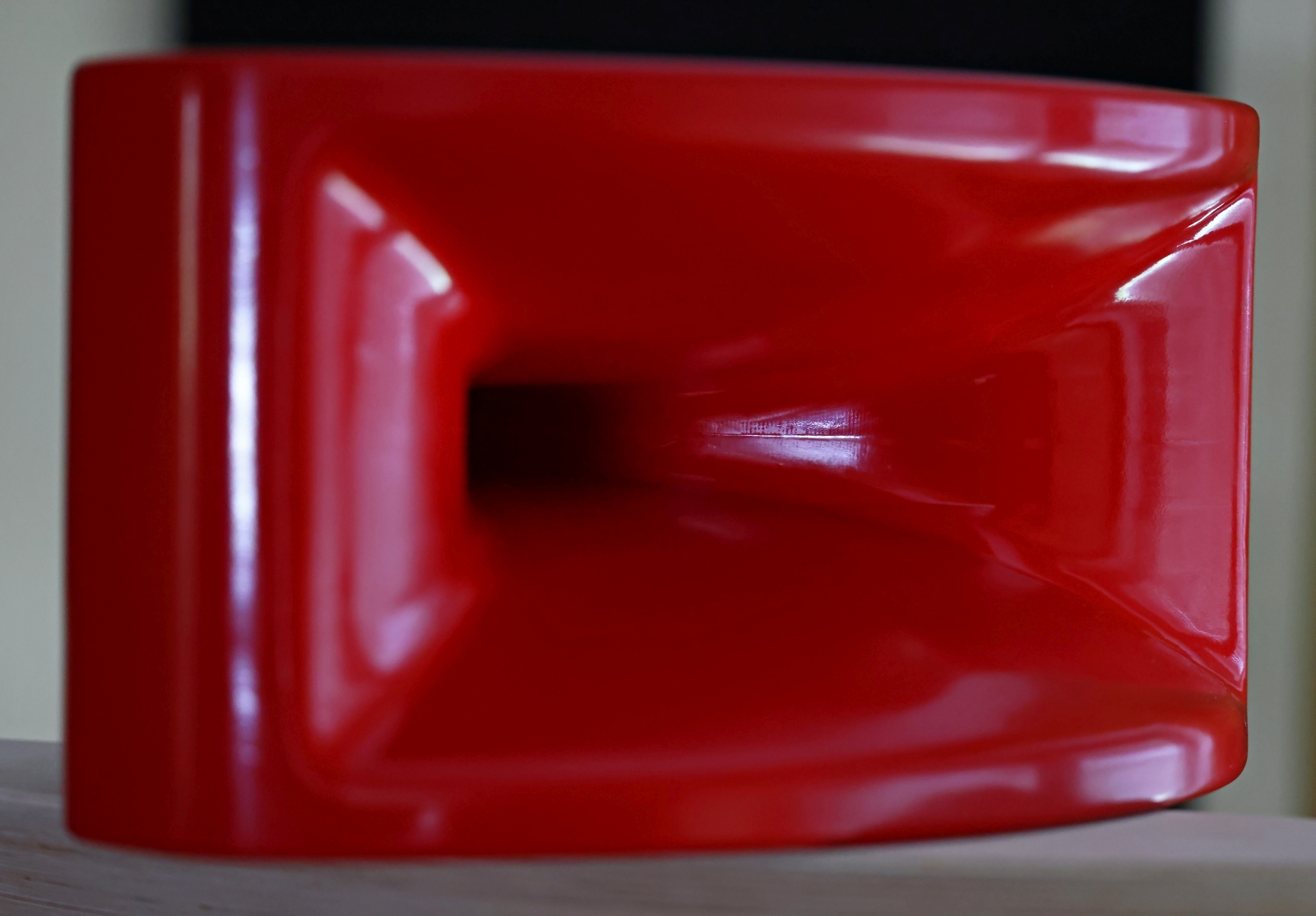
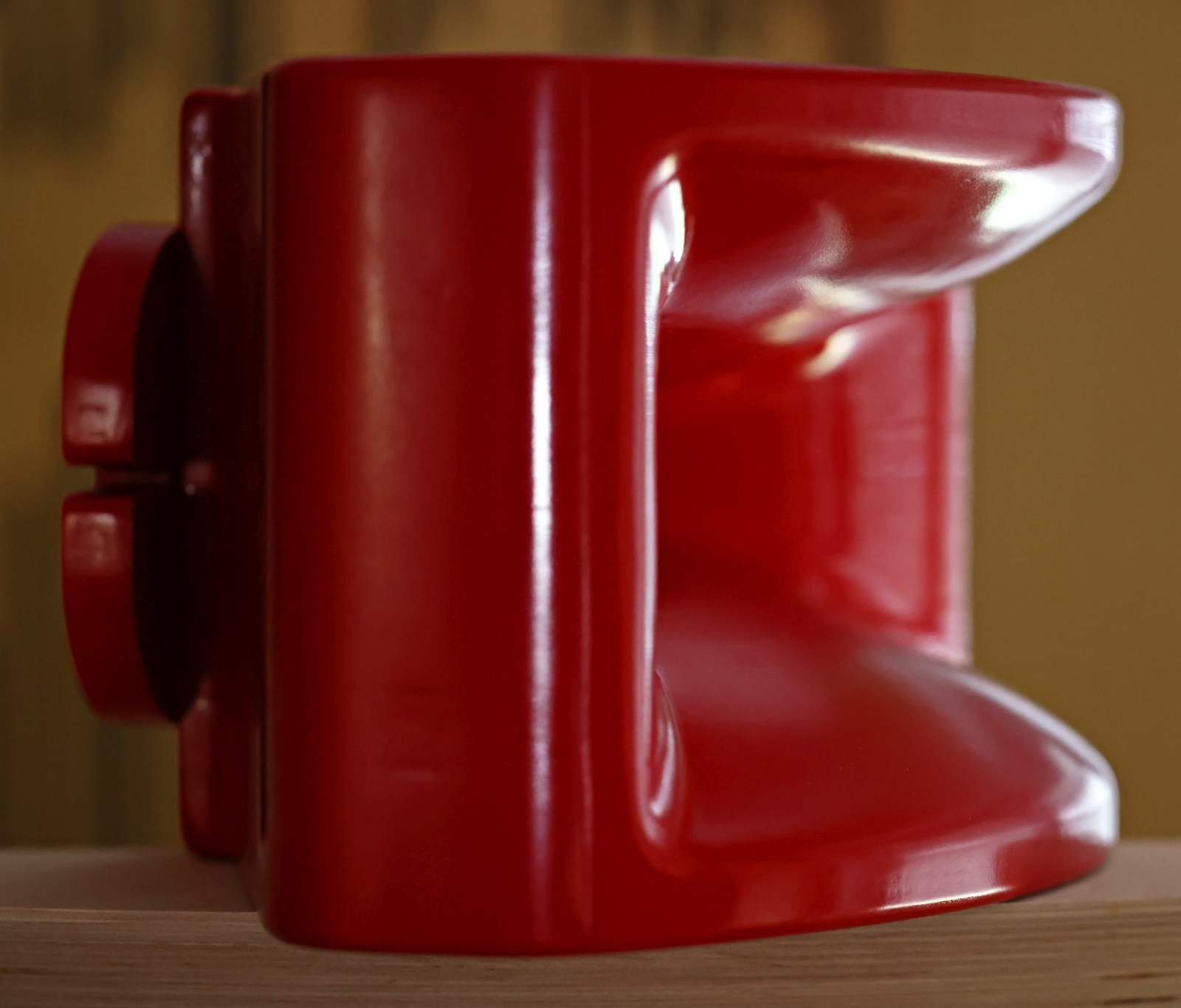
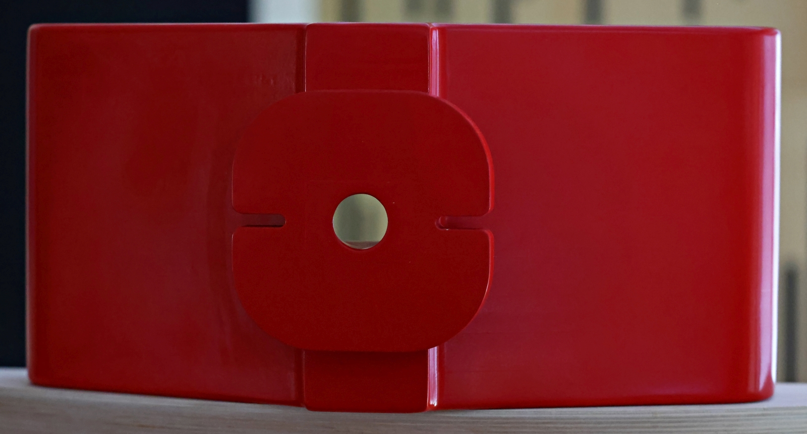
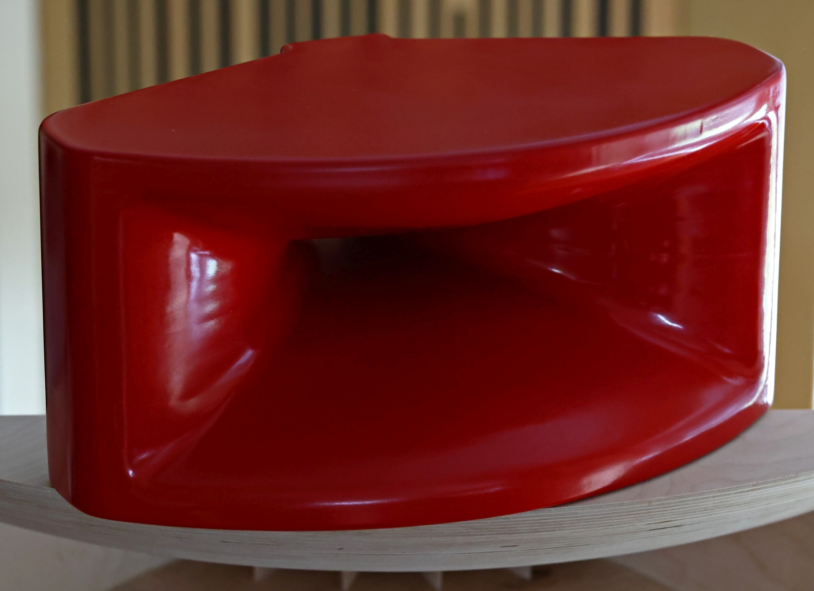
The shape of this prototype is derived from the use case of positioning the horn on top of a bass cabinet. Of course, different shapes should be possible for other applications or even a free-standing version.
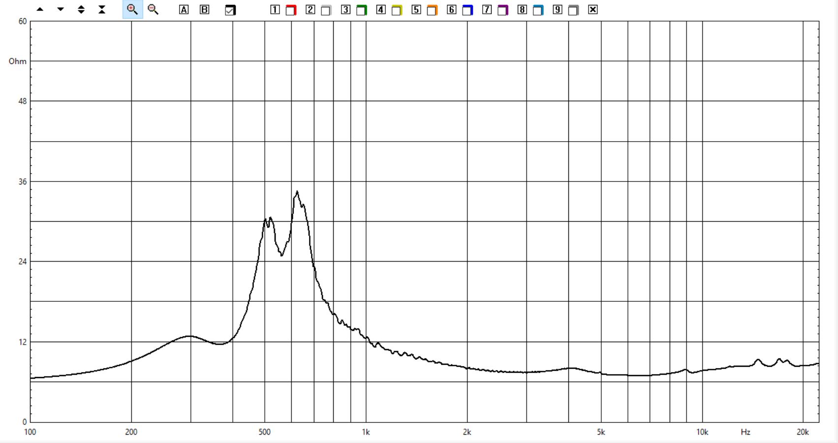
Again, the main goal was to assess how precise and trustworthy the BEM simulations are. For this purpose I bought an extra compression driver from Faital Pro, the HF108. This driver seemed like a good match for my new horn. All measurements presented here were done with CLIO pocket. Over the time I have established my own workflow which always starts with two impedance shots. One for the free-air setup and the second for the driver attached to the horn:
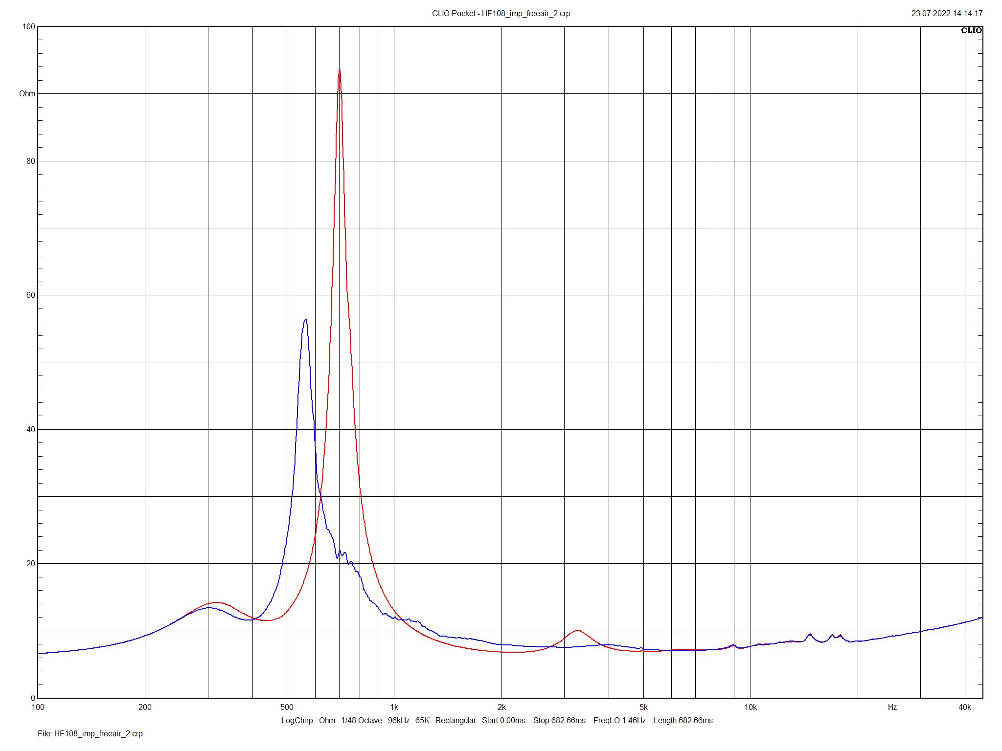
HF108 impedance. red=free-air; blue attached to William Neile horn.
Wow, what a nice and even performance. Just a single largely damped main peak and almost no visible side peaks which indicates a resonance free performance. The attentive reader may recognize that the small side between 2k and 3k has disappeared nearly completely. This is a great impedance performance and at the same time proves the very good match of driver/horn. Only to demonstrate how good these results are here is the impedance of the same driver attached the LTH142 horn:
HF108 impedance attached to LTH142 horn
There is an ugly double peak which indicates a resonance. There is also a small side peak visible. I will not blame this horn but imo it has a too small mouth area and the underlying tractrix profile is not a appropriate for very good directivity control.
The next step is usual to record the frequency response with the mic near the mouth. This is a good method to see the pure horn performance but always bear in mind that the natural baffle step loss is not included here. For lower frequencies the horn turns into a spherical radiator and if the mic is moved away from the mouth there will no longer be such a flat response:
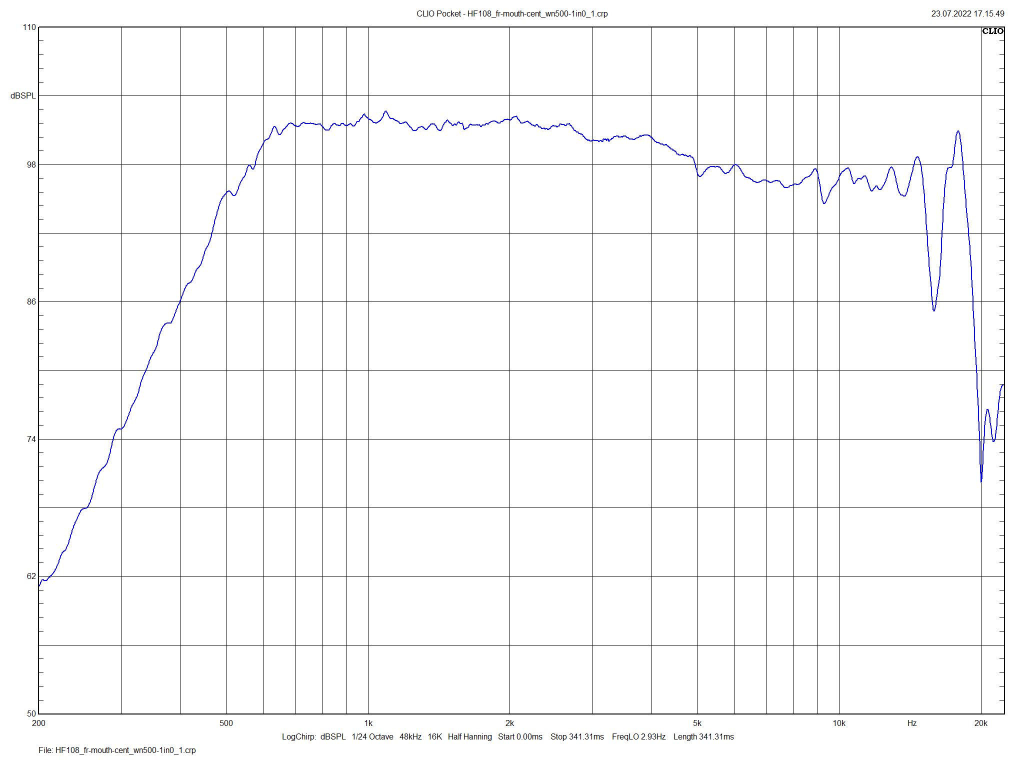
HF108 frequency response attached to William Neile horn (@mouth)
What a nice performance and full output level down to about 600 Hz! This seems all the more surprising since this is “only” a 1 inch driver. The horn was designed to provide full acoustic loading down to about 600Hz and this measurements again prove the simulations.
In most cases when horns are optimized with respect to loading they show poor directivity control. The worst case I have ever investigated with respect to this was a pure tractrix profile. Not so with the new William Neile ALO horn. For the measurements I moved the mic to about 75cm away from the sound origin. I only have a small room for my hobby and this should provide reliable results and at the same time avoid too much reflections in my room. The following results are gated to about 4.5ms which already significantly invalidates the LF region. Nevertheless, the lowest curve at 30° still show comb filter effect of the mic position with the floor. But what is interesting for us here is the HF part and this is excellent with respect to horizontal directivity. The curves are more or less a parallel shift with a very slight spread towards HF. There is also no visible knee what we observe for certain horns which loose directivity control abruptly from a distinct frequency on.
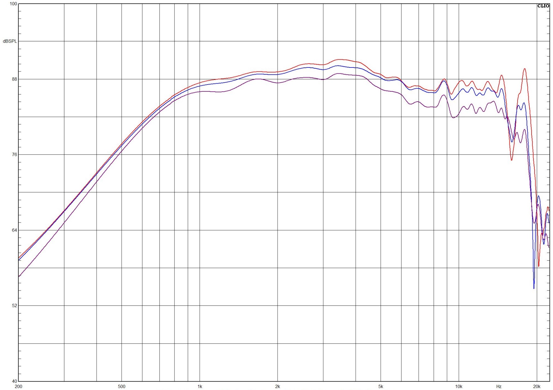
Angular Frequency Response of HF108 attached to William Neile horn at about 75cm. red=0°; blue=15°; violet=30°
CLIO pocket has a nice feature to make a polar diagram by using several angular measurements and merge them in a normalized form:
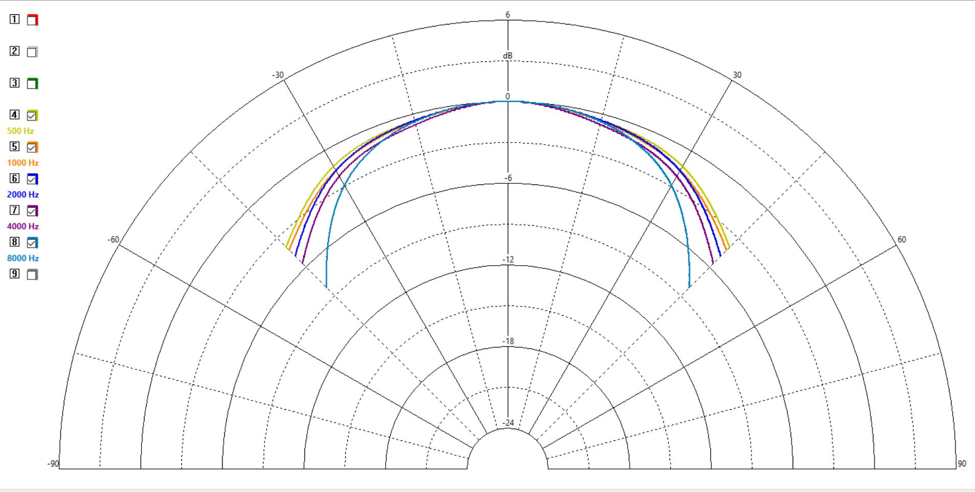
Horizontal Polar for HF108 attached to William Neile horn
This is a great and smooth performance for directivity control with absence of any visible knees. The agreement with the simulations is astonishing good so that I left out the cumbersome vertical polar measurements. The lessons learned are that the simulations are very trustworthy so that for the future horn projects the creation of a prototype could be omitted.
I am extremely satisfied with the measurement results of the first prototype! Thank you again Jaroslav for supporting my work. I am convinced that we will continue our cooperation successfully and hopefully with great pleasure.
Stay tuned as the next steps are listening tests. A pair of William Neile horns have to be built. There are two basic options, 3D printing or milling a pair from wood. It seems that the 3D printer will be faster but my preference for an ultimate setup is still a pair of wood horns.
In due course of time I will publish authorized sources who can be trusted if there is any interest in purchasing William Neile horns based on my final designs. It should also be mentioned in this regard that the William Neile ALO horn profile has meanwhile been improved, especially for the vertical flare. I also realized the William Neile ALO horns using a super ellipse formula which means that the whole range of elliptical mouth to nearly rectangular mouth horns are possible by adjusting the Lamé exponent of the super ellipse. All different variants perform very similar so it ends up as a matter of taste what to choose.