The second part of this article series deals with 1in4 (1.4 inch) William Neile ALO horn. This is the next logical step on my agenda. Also because the new 1in4 William Neile ALO horn is supposed to replace my current TH4001 which is a good sounding horn so the expectations are set quite high. The category of the so-called fin horns seems to me to be quite popular and their good sound properties are usually reported. However, I am of the opinion that the known underlying assumption for the construction of fin horns, especially the fin shape and arrangement, does not lead to a coherent wavefront over all frequencies at the exit of the individual channels. I have developed an improved version of different curved fin arrangement which implements equal path lengths of each channel together with the right and exact opening angle for proper exponential acoustic loading, but this is another story. So to speak the TH4001 is a good performer but has some serious design issues. The William Neile ALO horns use what I call natural dispersion instead but with it’s own limits one has to accept. What I want to say is that it is not possible to achieve such wide radiation for a very low-loading horn similar to a fin horn. In my opinion, this is not necessary at all for use in normal listening rooms. But many are somehow still of the opinion that some kind of cinema horns with extremely wide dispersion should be set up at home but these were intended to reach hundreds of people in a large cinema hall with evenly distributed sound impressions at every single seat. A slightly narrower dispersion can definitely be an advantage, especially in smaller listening rooms and when only a few listening positions in the room have to be considered. The intrinsic problems of fin horns, which are related to the the individual channels (shape, length, arrangement), such as cavity resonances or excitations or the suboptimal addition to a coherent wave front, cannot occur with a natural dispersion horn. For example, anyone who doubts that e.g. 30 degrees of even radiation can be sufficient should mark this angle with two strings on the floor from each loudspeaker to the listening position and preferably with the loudspeakers angled slightly inwards and then look at the area of even radiation delimited by the strings on the floor. My 1in4 William Neile ALO horn will achieve about twice as wide dispersion in the horizontal plane.
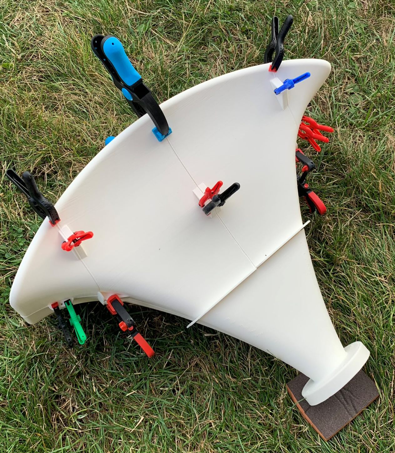
To give a quick preview of what kind of horn to expect, Jaroslav has started 3D printing the first pair for his own exercise. The horn is of course far too big to print in one piece, so it was split into several smaller pieces. To be honest, I was a little skeptical about the results but here is the first try with initial printer configuration parameters and a quite cost effective PLA material:

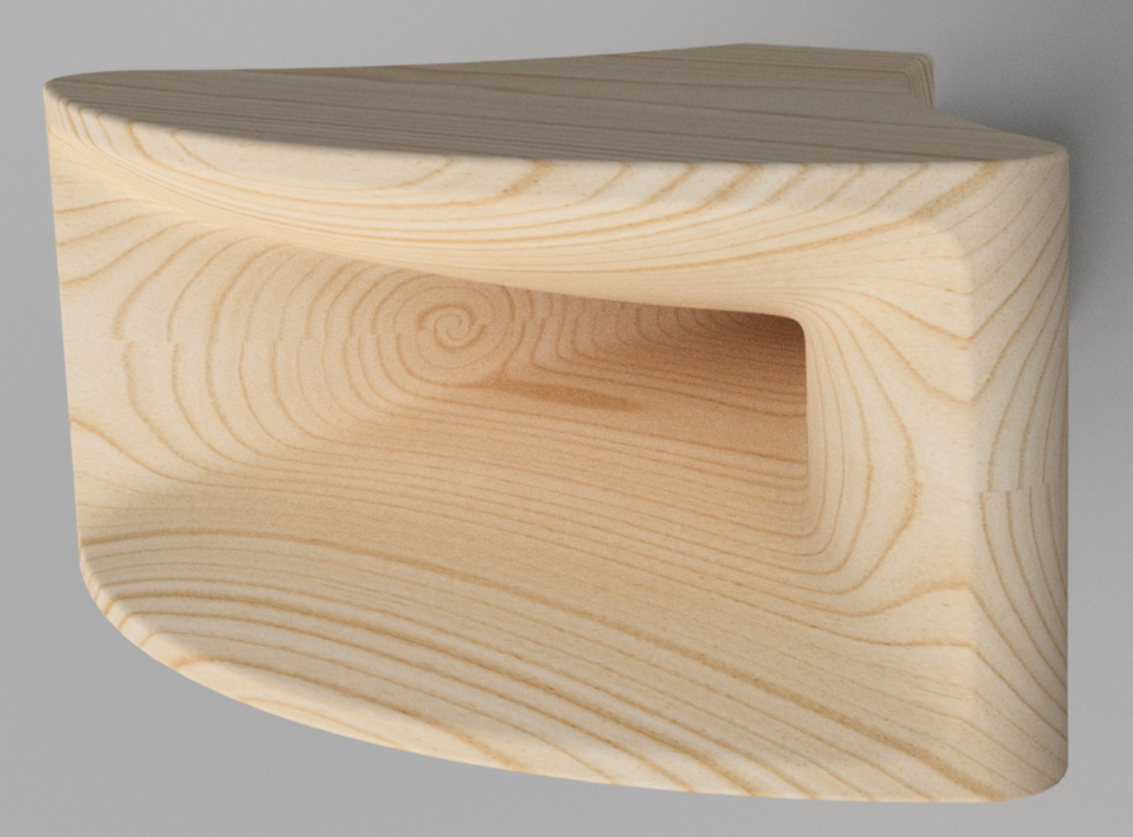
Simply awesome! I have played around myself with CAD software and this is the result with a rendered wood finish similar to the 1in0 prototype construction:
The 1in4 prototype is based on the BEM optimizations done with AKABAK and visualization of the results with VACS. As in all cases before constant velocity drive was used for the simulations. I will give again a link to a more detailed discussion about BEM “constant something methods”. For such a large horn compromising have to be made with respect to mesh resolution as calculation times rise exponentially with the number of elements. So I still think that some HF issues are still related to the model and I expect the real horns to perform even a little bit better.
The original goals for the 1in4 design were predominantly full acoustic loading down to about 350Hz or even something lower and a horizontal dispersion of about 60 degrees in the horizontal plane up to midrange or even higher frequencies. This is how the resulting 2D horn profile looks like:
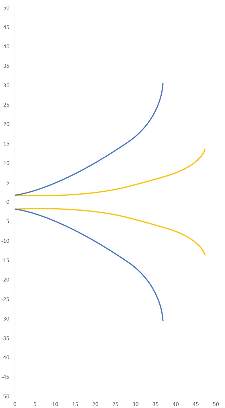
1in4 horn 2D profile.
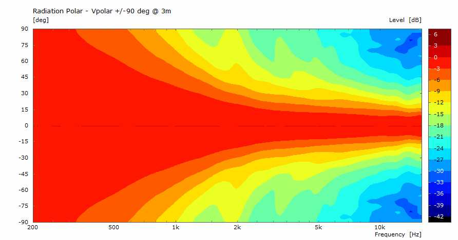
This is a really large horn but form follows function and goals. The corresponding BEM results are more than promising with respect to the mentioned design goals:
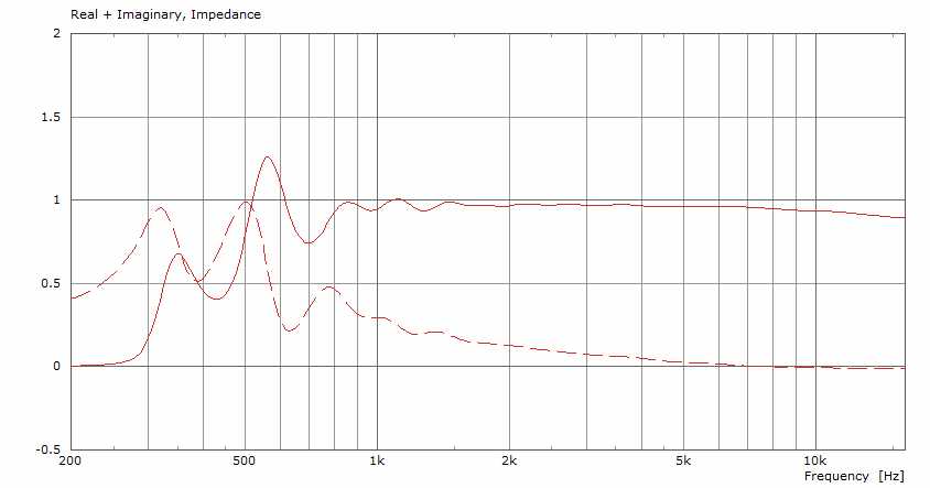
William Neile ALO 1in4 horn radiation impedance.

William Neile ALO 1in4 horn horizontal polar.
William Neile ALO 1in4 horn vertical polar.
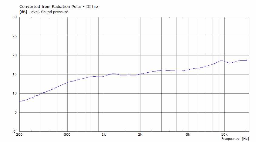
William Neile ALO 1in4 horn horizontal DI90.
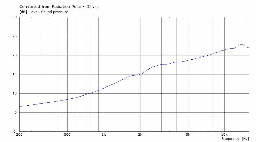
William Neile ALO 1in4 horn vertical DI90.
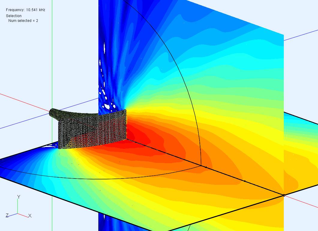
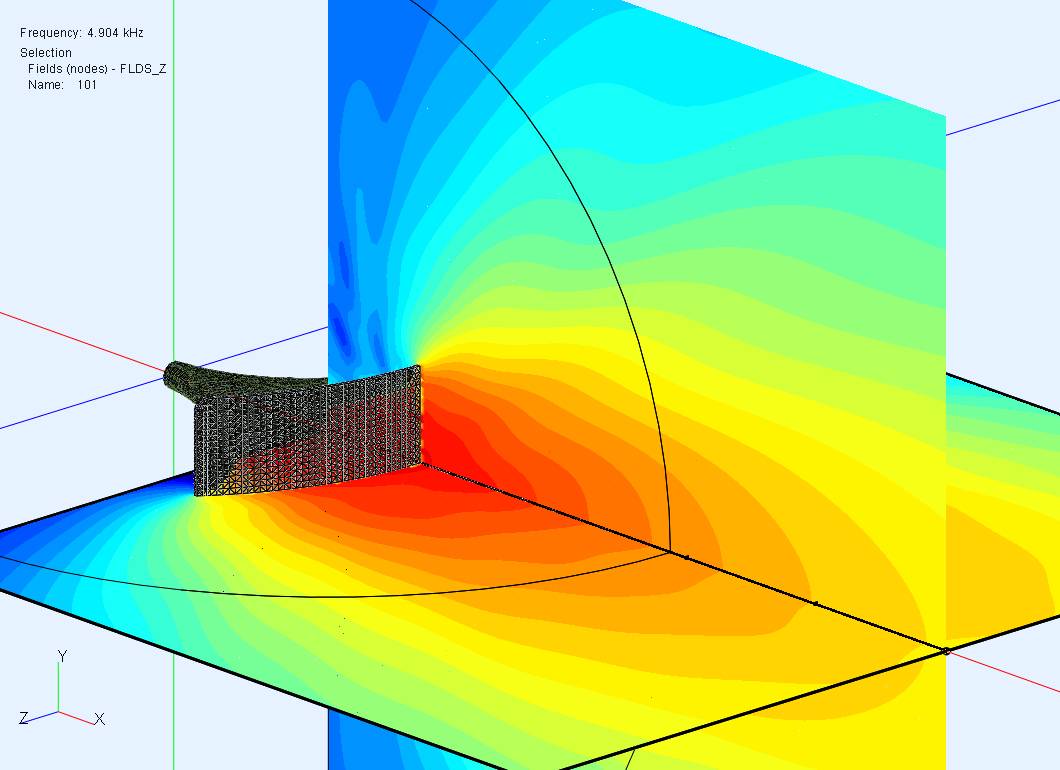
And finally, most probably you will never find sound pressure level fields for any comparable horn but I will show some extracts here to show how evenly this horn is performing:

Sound pressure (Level dB) fields at 500Hz
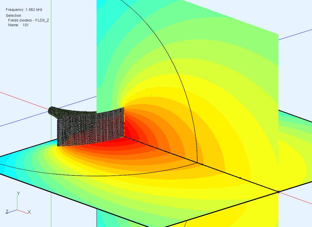
Sound pressure (Level dB) fields at 1kHz.
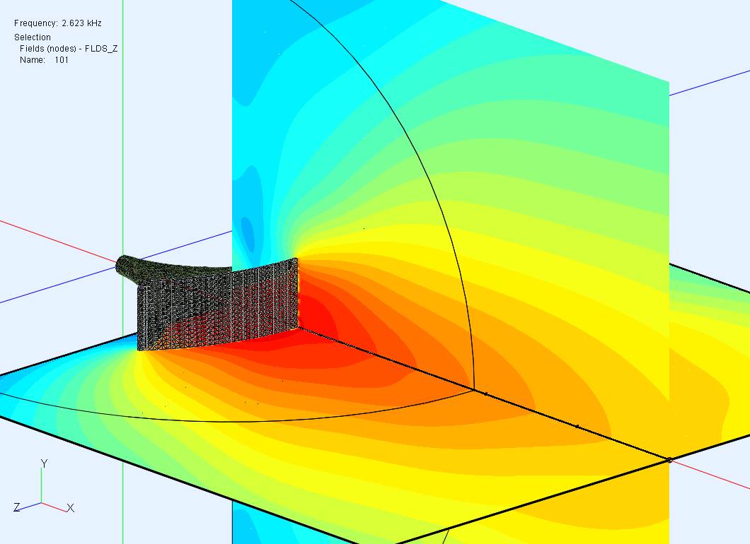
Sound pressure (Level dB) fields at 2.5KHz
Sound pressure (Level dB) fields at 5kHz.
Sound pressure (Level dB) fields at 10kHz.
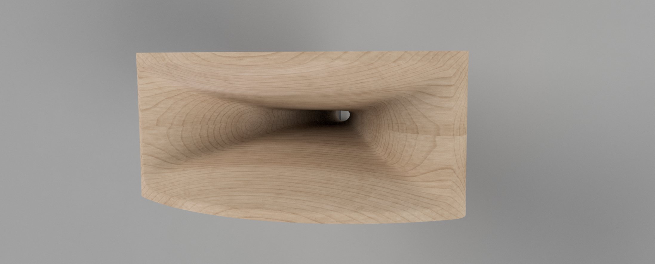
I am more than happy with the results and how my new William Neile ALO horns perform for different driver types. Also this 1in4 horn is free of any waiste banding. The horizontal plane looks almost perfect to me. The overall performance is even and smooth without any significant issues. Based on this results even a 2in0 version seems to be possible with a slightly reduced goal with respect to dispersion as such a horn would be more than 60cm long. But as a next step the first listening tests are planned. I am quite optimistic that these will be very satisfying especially when I receive my ultimate pair milled from solid wood, maybe like this: