
For some time now I have been investigating for the so-called fin horns. And for over a year now I have been able to generate complete point clouds for such horns. I myself own a replica of the TAD TH4001 horn and I think these horns sound very good and load the driver perfectly down to the lowest octave of the usable range of the driver. A passive crossover can therefore be implemented without significant problems.
What has always surprised or bothered me about these fin horns is the straight construction of the fins, which start on a section of a circle near the throat. My understanding is that a point sound source at the intersection of the two side walls is assumed. But what if the arriving wave front is not curved like the fin start circular arrangement? And what is happening in the small “pre-chamber” before the fins? My initial idea for a new approach was to use a mathematical function that starts directly at throat and which is curved and an analytical expression of the functions arc length is known. The resulting fins should start at throat, they should be be curved and they should end at the same path length along the curved trajectory. At this time I came across with a function discovered already in the 17th century that is named after William Neile (Link1) as Neile parabola. Another well known name is semi cubical parabola (Link2). It was the first algebraic curve to have its arc length computed (Link3). The semi cubic parabola bears an interesting property that it is an isochronous curve of Leibnitz (Link4) . All in all a very attractive looking function and worth to try it as a horn function. This article deals with my way to use the Neile parabola as horn function.
But let us first come back to fin horns. The traditional fin arrangement looks like this:
And the resulting horn shape in the horizontal plane is radial like. You will also notice the end flare which is present for Yuichi horns but not for the original TH4001 which has straight side walls.:
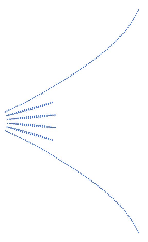
As already written the fins are arranged on a section of a circle generally with the circle’s centre where the two side walls intersect behind the horn. What I intended was another assumption of a nearly flat wave front at throat. For the 18sound ND4015Be I was told that this is nearly the case with it’s special phase plug design. My new idea was to have the two side walls und each fin trace as a Neile parabola equally spaced to each other and which was very important to me all trajectories should have the same arc length (path length) for the horizontal part of the horn. The fins thickness and the vertical expansion will then account for the desired wave front surface area expansion. The goal is to have a small finite fin thickness at throat following the given expansion formula. To reach this goal was a little tricky but an offset definition and a re-normalization resolved this issue while holding the vertical expansion of the horn constant for an infinitesimal length. The most outer Neile parabolas which represent the horn walls must not start at an opening angle of zero. In fact, each different expansion formula or parameter setup yields a different opening angle. The tangent of the Neile parabola is also known as analytical expression and I use the tangent at a pre-defined horn length as input parameter to calculate the scaling parameter of the Neile parabola. In contrast to my previous posts, I will not publish any mathematical details. As an example for a horn with 4 fins the results is the following:
The functions are equally spaced at throat and also at mouth. Some mathematical “ming mang” and number crunching is necessary to reach this goal. It’s not an intrinsic property of the Neile parabola. The horn shape and the fin arrangement looks quite different with this approach (here for simplicity without end flare):
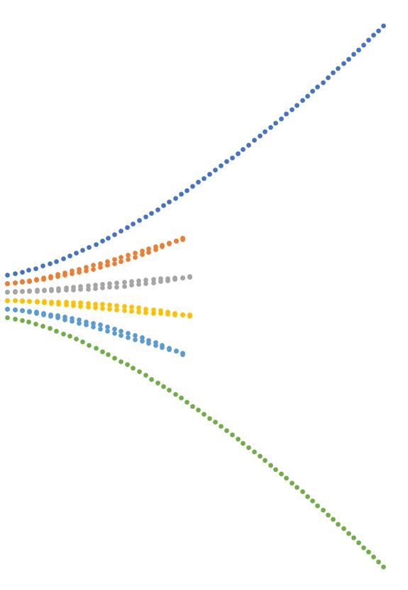
Exactly the same algorithm can be used with an increased number of Neile parabolas to evaluate a construction wave front in the horizontal plane:
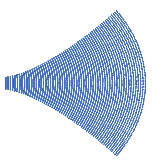
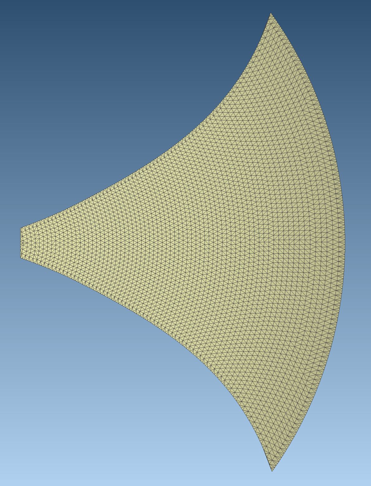
And furthermore these horizontal construction wave fronts will be at the same time the boundary for the horn in this plane. The shape is similar to a radial horn but by using Neile parabolas with the same arc length we end up different from the radial horn with a quasi isophase path length for each trajectory from throat to horn mouth. Finally, a BEM simulation could show if such an assumption is valid to use as a horn function with sufficient quality for loading and dispersion. This will be covered in forthcoming posts.
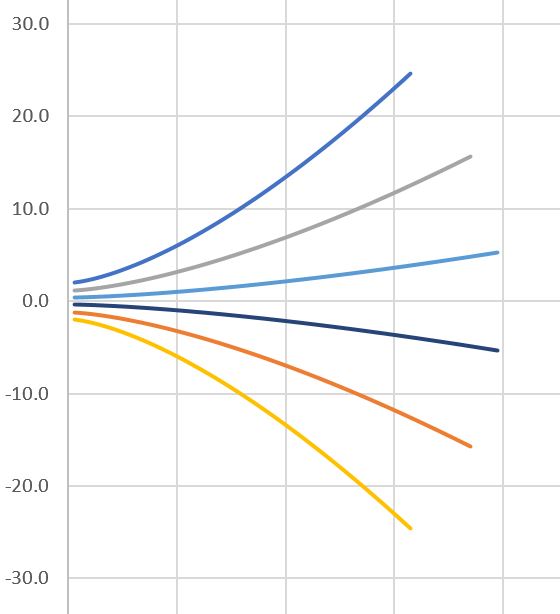
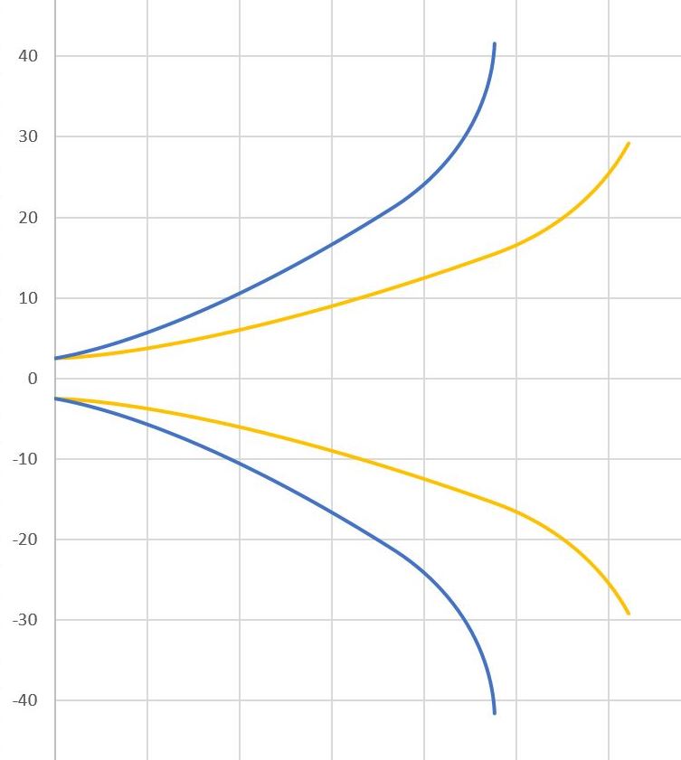
Now, I will only show how a such William Neile horn looks like. To keep it simple I initially leaved out the fins and did some tests with pure Neile parabolas as proof of concept and I have to say that the results surprised me a lot positively. The remarkable thing is that the Neile parabola yields much better directivity control because of it’s basic shape. The following example is a really big horn or waveguide whatever you want to call it. For a simulation size does not matter so much except computation time. The added end flares avoid the so called waste banding or midrange narrow and they are essential to give good results. The horizontal and vertical expansions are different while the horizontal plane (blue) builds up the basic horn shape and the vertical function (yellow) adds the height of the horn:
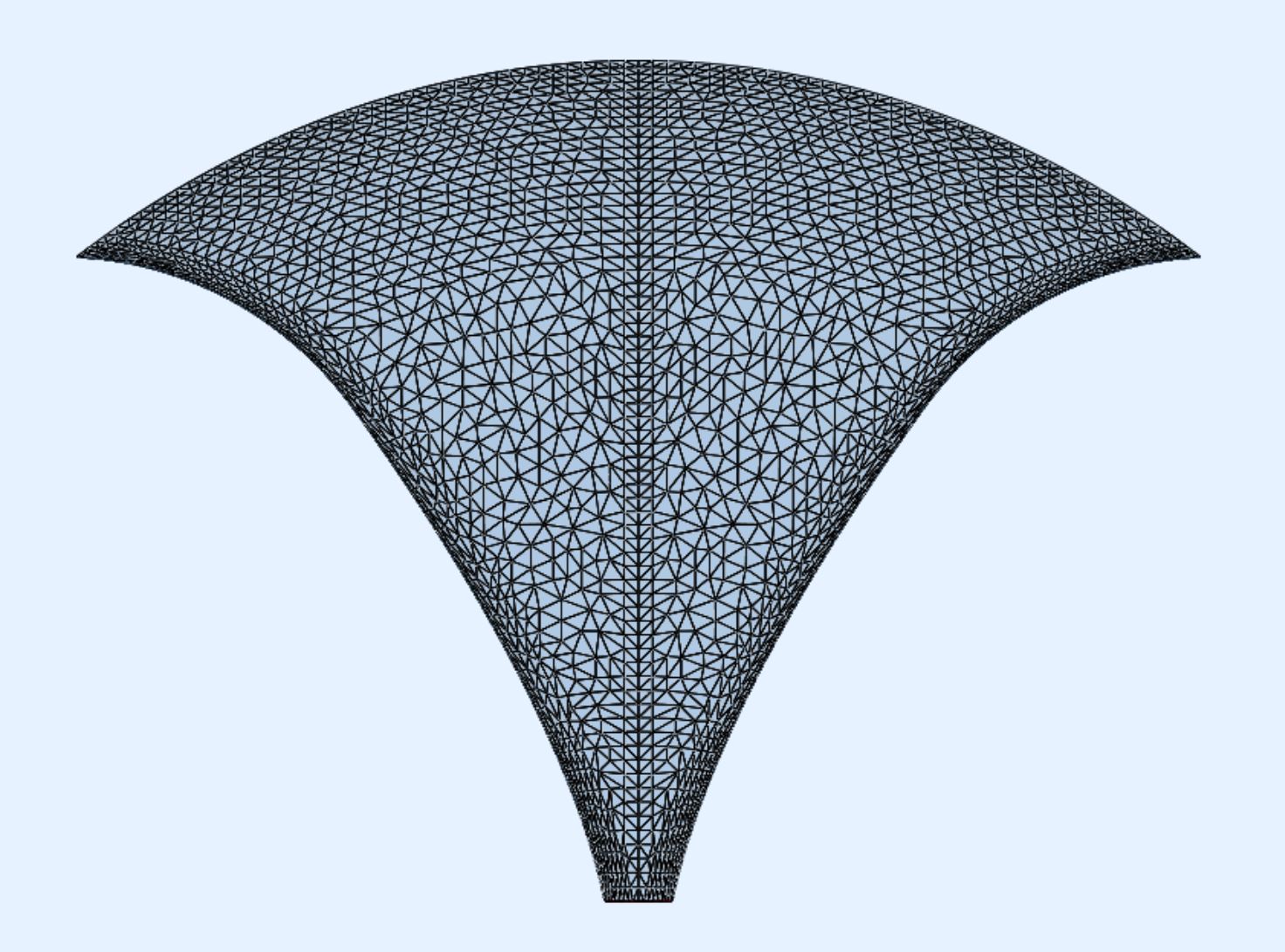
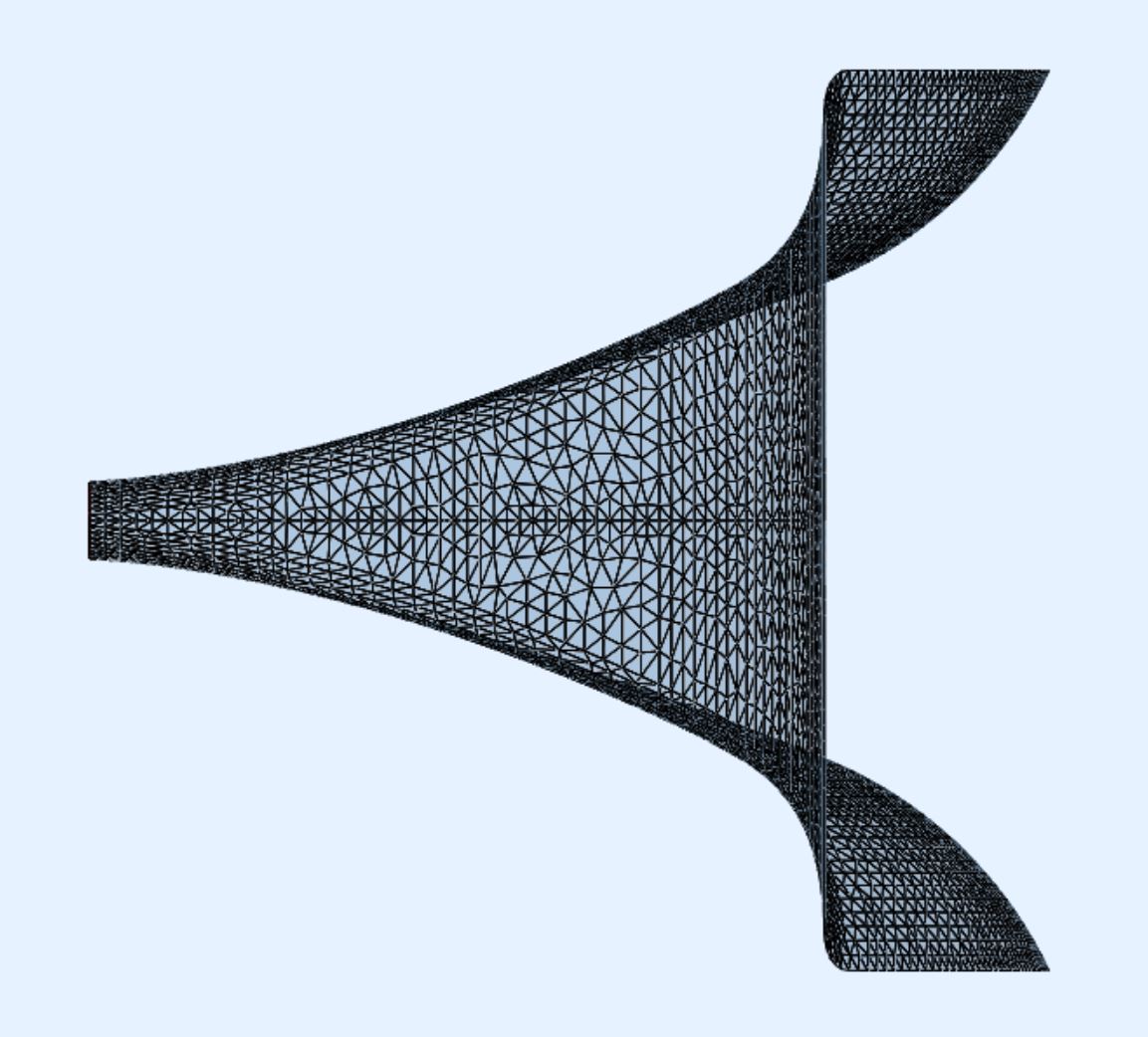
This example is a construction of pure Neile parabolas with a distinct offset at throat. It does not follow any expansion law with respect to wave front surface area expansion and was made as proof of concept So the loading capabilities will be similar to a waveguide. Later on there will appear also Neile horns which respect a pre-defined expansion formula and will be optimized for perfect loading up the lowest possible frequencies while preserving greatly the dispersion characteristics.
With the Neile parabola I started to find a way to construct curved fins which all start at throat and have the same path length and ended up now with a new category of horns without fins. Stay tuned for more articles in this series.