
In two previous posts I presented my PETF algorithm and JMLC inspired horn calculator. Assuming that many of my readers are familiar with the native JMLC horn performance like loading or radiation polar it should be a common acceptable consensus that JMLC horns do not belong to the so called constant directivity (CD) category. Towards higher frequencies they tend to slightly beam which is because of the curved horn walls. This might not be an issue for some applications or some people might even like this behaviour but as general rule of thumb the lower the horn cut-off value the longer the horn profile will be and the smaller the initial opening angle both causing an increasing tendency to narrow the dispersion of higher frequencies. A more focused dispersion of higher frequencies might be an advantage in small environments if it is fairly constant or if the intention was to compensate the natural roll-off of most compression drivers but generally a design goal of wider dispersion is one of my personal preferences. More precisely, one of my main goals is to find a good compromise between good horn loading and good directivity control.
There can be found some BEM simulation examples for round JMLC horns in the web that clearly show the increasingly more narrowed dispersion towards higher frequencies especially for the lower loading versions with 350Hz or lower cut-off. On the opposite JMLC horns shine if the target design intention was mainly a nearly perfect horn loading down to the desired cut-off frequency or by looking at the smoothness of radiated wave fronts when the formalism inherited roll-back is present.
I already presented that the PETF algorithm produces a faster opening of a horn profile while straightening the horn walls. In this article I will investigate what horn properties we can expect by applying PETF to a given profile.
In this post I will present two variants with pronounced PETF applied in order to investigate what are the benefits or disadvantages by using this algorithm. Therefore, I have selected a common round JMLC 300Hz cut-off horn with T=0.7 and 35mm throat diameter as optical reference for the basic profile:

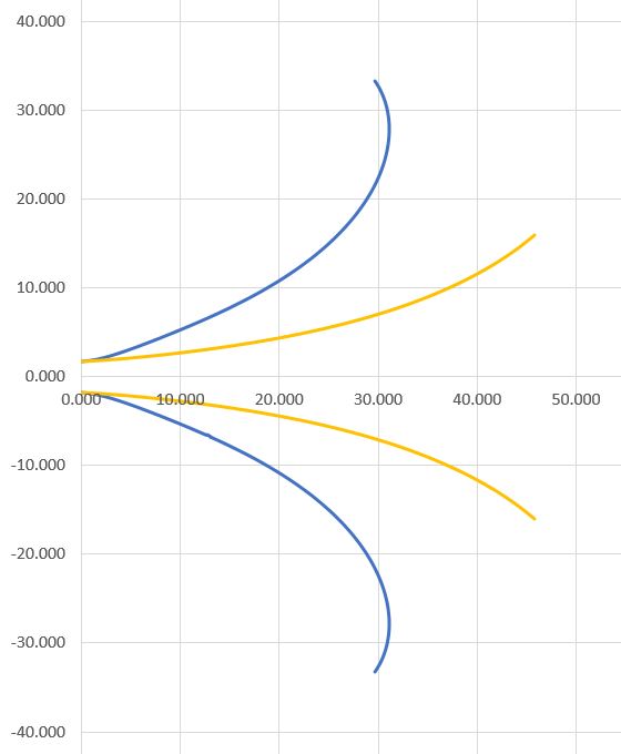
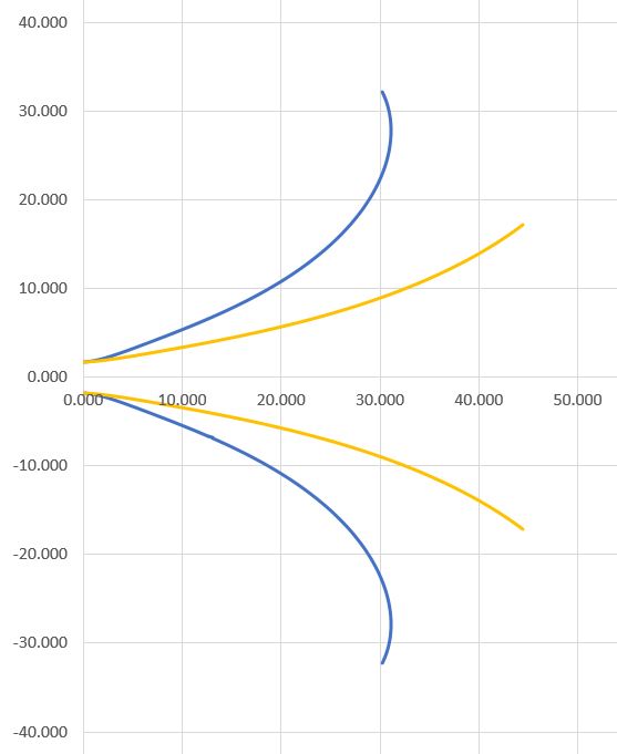
Then PETF algorithm is then applied with the following parameters: T_0 = 0.6, T_{add}=3.5, f_{mult}=2 leaving the cut-off parameter at 300Hz. The resulting profile has changed significantly:
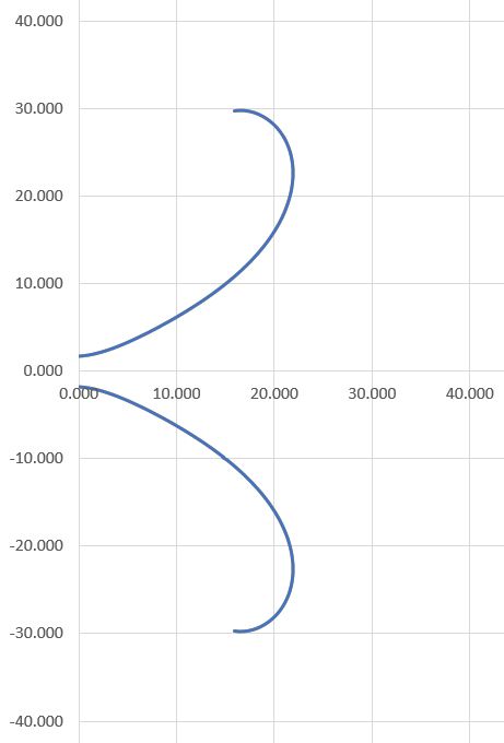
JMLC PETF 300Hz horn profile
What is immediately obvious that the length of the horn has shortened a lot but the width is nearly the same. This a common rule of thumb that the cut-off parameter greatly determines the width of the horn and PETF does not significantly change this property. A similar behaviour with respect to horn length and width can be reached by using a higher but constant T-factor but without the flexibility of PETF as dependency of the main horn axis.
Many thanks again to DonVK who prepared the BEM models. I appreciate his support and the discussions very much.
For the simulations we used AKABAK and VACS viewer from R&D Team Software Development. This is an incredible useful and nice software for this purpose. I thank Joerg Panzer again for supporting our work.
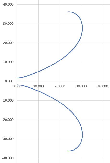
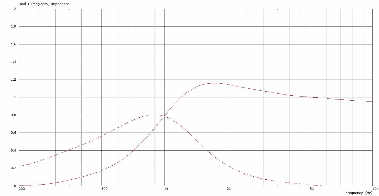
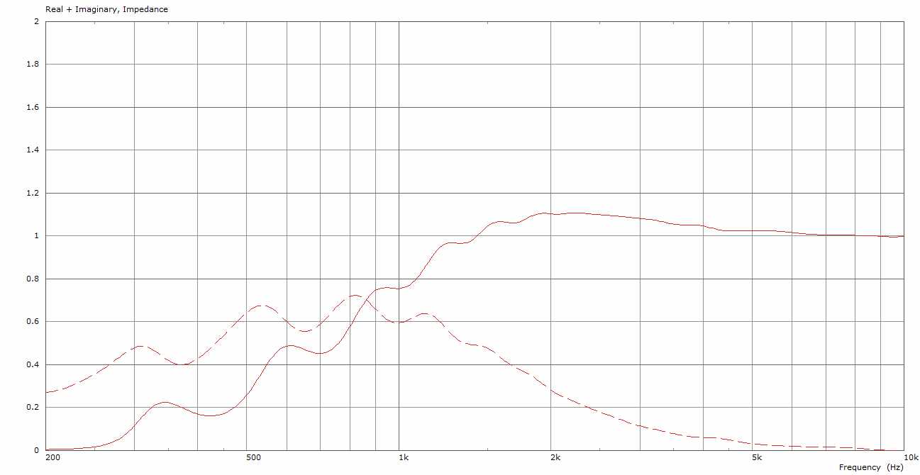
Let us start the discussion of the BEM results with the major trade-off which should already be obvious by the considerably reduced horn length: a loss of loading capabilities. The cut-off parameter seem to have lost it’s original meaning:
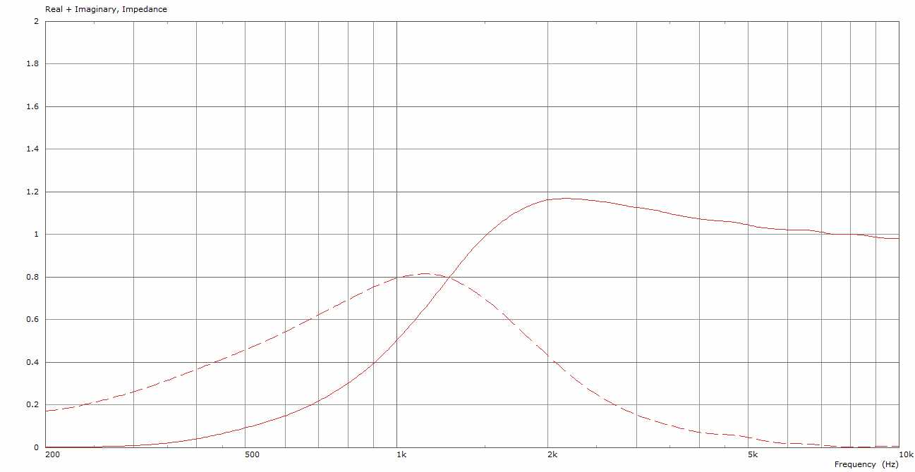
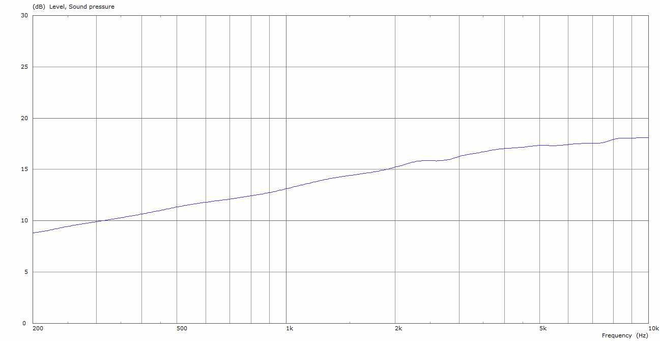
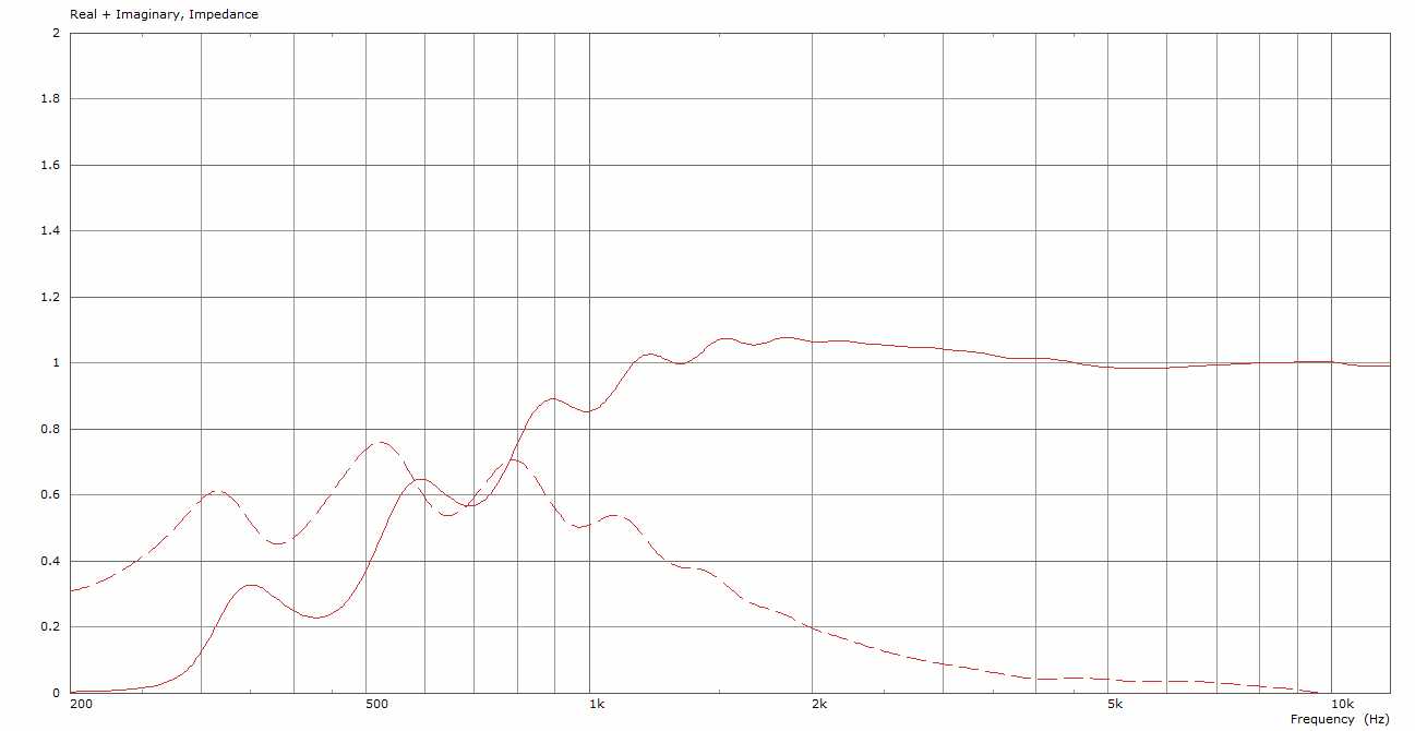
JMLC PETF 300Hz radiation impedance

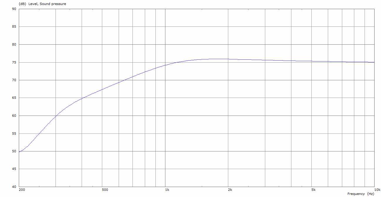
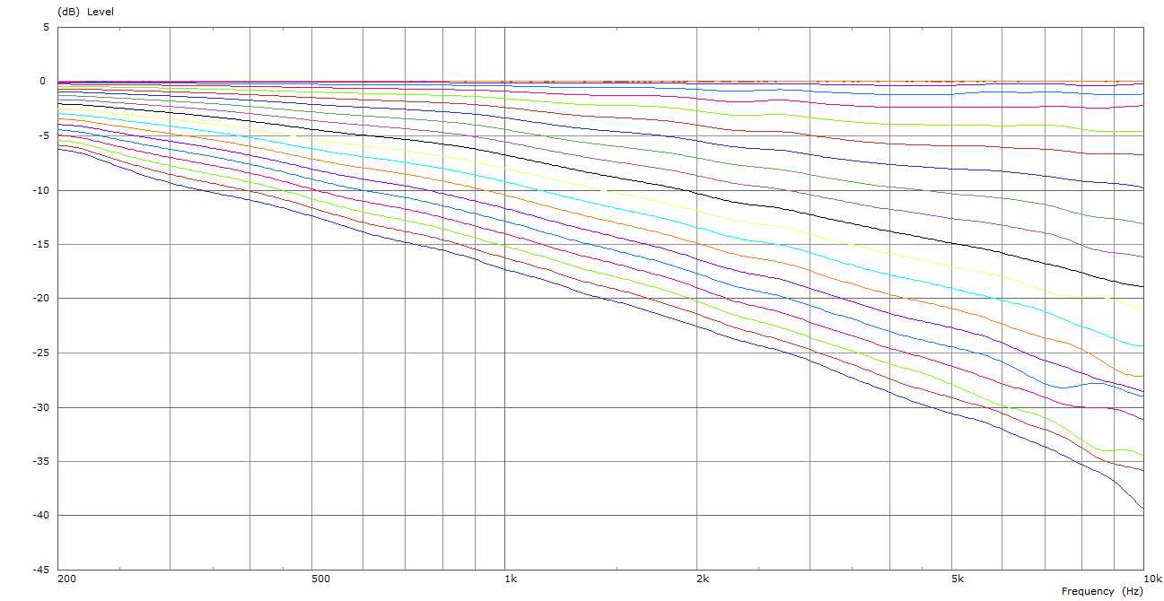
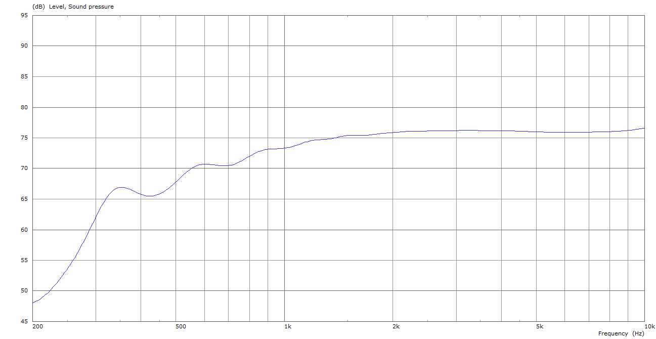
JMLC PETF 300Hz power response
The target cross-over frequency is at least one octave higher and the impedance and power response look more like a conical waveguide with end flare. One might say something between JMLC and a conical profile. But it should be mentioned that the roll-off to lower frequencies is more gracefully with about 6 dB per octave at the beginning. We clearly have lost horn loading capabilities but the roll-off is quite smooth. What have we gained? Directivity control!
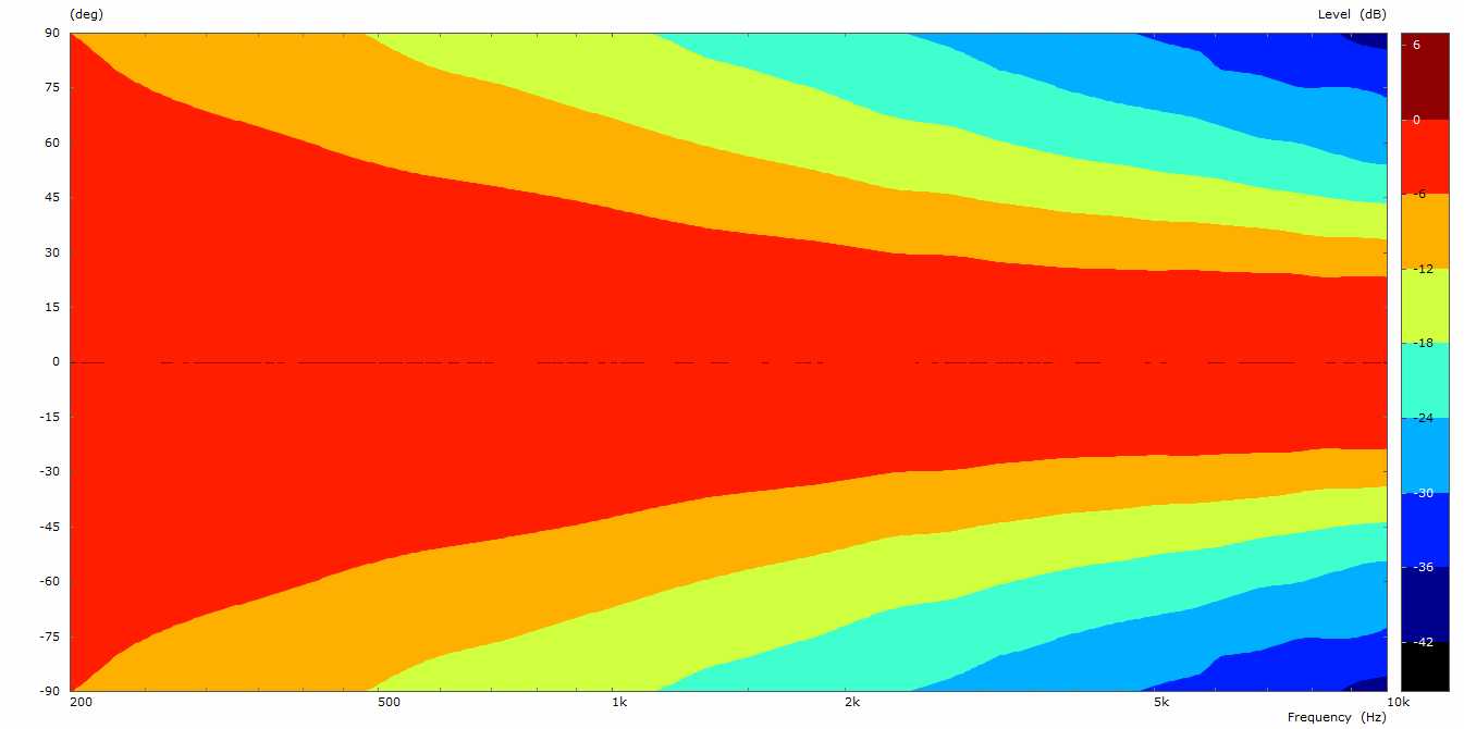
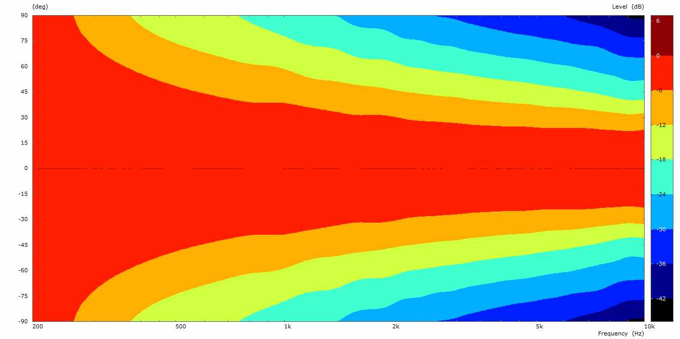
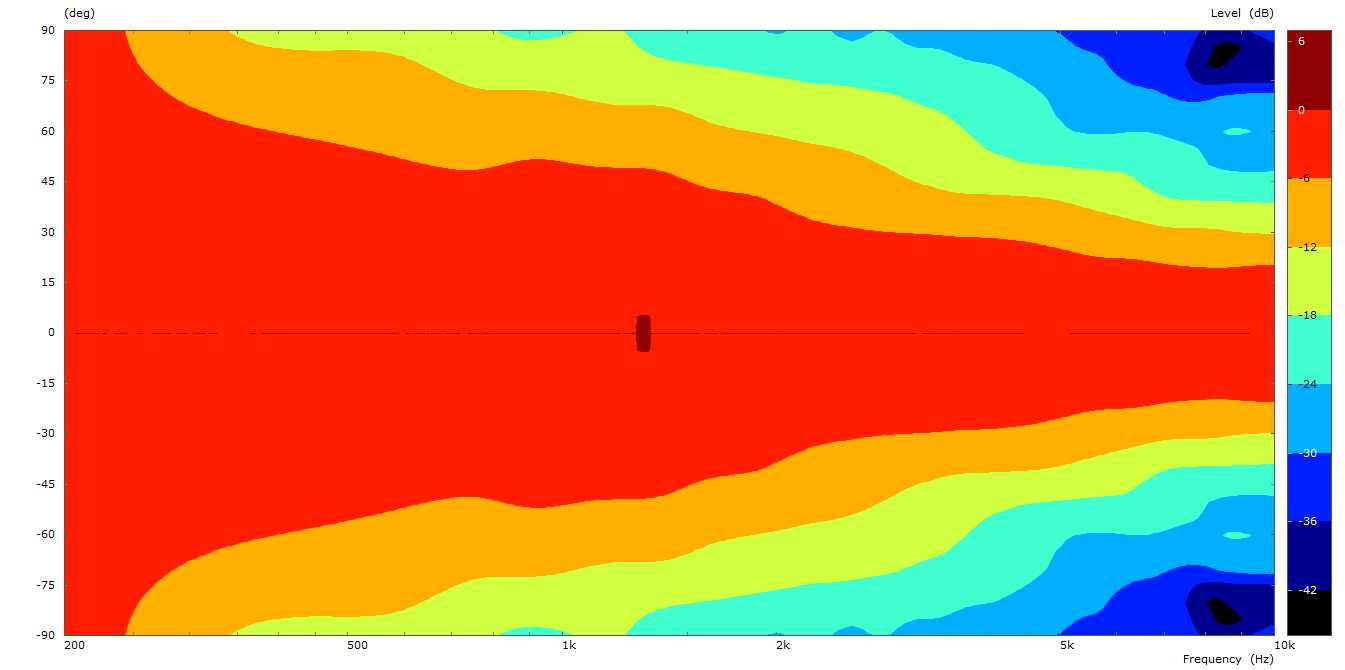
JMLC PETF 300Hz radiation polar (6dB step)
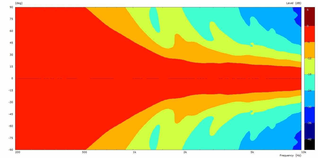
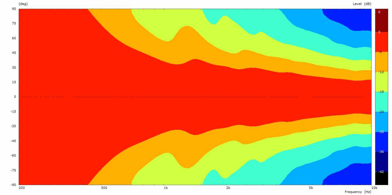
JMLC PETF 300Hz radiation polar (3dB step)

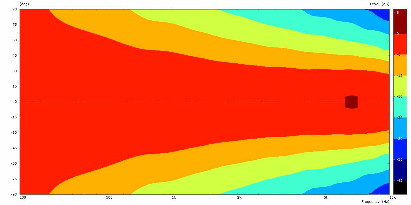
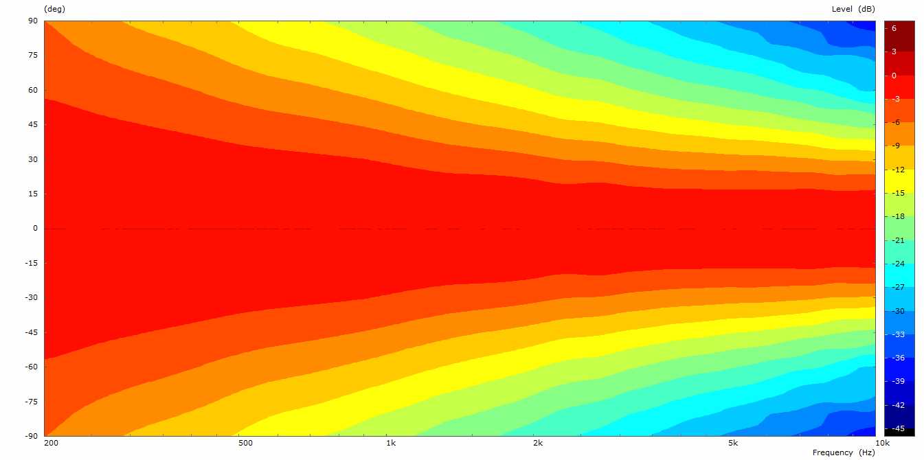
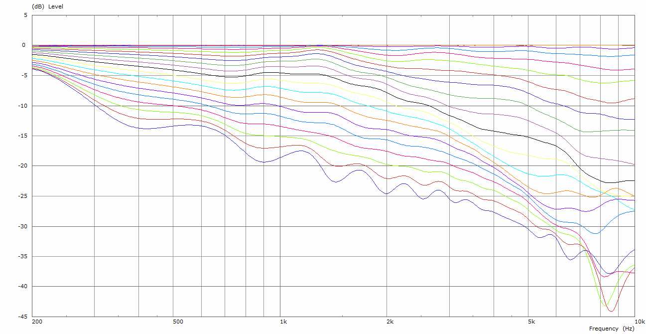
JMLC PETF 300Hz polar (0-90, 5 degrees step)

JMLC PETF 300Hz Directivity Index (DI)
I would say that this performance is really good and very smooth. Nearly 60 degrees for the -6dB line is much better than I expected. It should be mentioned that the horn profile roll-back plays an important role for this smooth performance as free-standing horn. If the horn is part of an cabinet the profile could be terminated already at 90 degrees reducing considerably the width of the horn.
But is it possible to get some loading capabilities back? The answer is yes by lowering the cut-off parameter but at the expense of even more horn width. The second example has a cut-off value of 250Hz and the same PETF parameters: T_0 = 0.6, T_{add}=3.5, f_{mult}=2.
JMLC PETF 250Hz horn profile
It loads a little bit lower but not by a big margin:
JMLC PETF 250Hz radiation impedance
JMLC PETF 250Hz power response
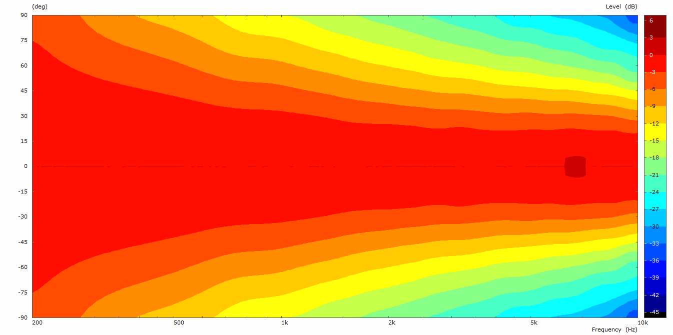
The directivity control is in the same league as the previous PETF horn, maybe slightly less control at HF but a little bit better control down to LF:
JMLC PETF 250Hz radiation polar (6dB step)
JMLC PETF 250Hz radiation polar (3dB step)
JMLC PETF 250Hz polar (0-90, 5 degrees step)
JMLC PETF 250Hz Directivity Index (DI)
Leaving the width size restriction aside I would choose the 250Hz PETF version as it has the better loading and a more even directivity control.
It has been shown that the PETF algorithm is capable of improving considerably the directivity control of a given horn profile at the expense of horn loading capabilities. For those who do not have the main focus on horn loading this might be a way to go. The presented horns should work safely well as HF horns with cross-over above 1k. Lower cross-over points should be treated with care not to produce driver distortions in that region. The more gracefully decrease of loading towards LF compared to exponential type horns might help here.
The parameters used for these examples represent quite pronounced profile changes in order to show clearly the effect of the algorithm. Although, even more steep profiles are possible. By using other less steep parameter sets preserving more the original curved profile many other variants between a pure JMLC horn the examples presented here are possible. A really nice playing meadow.
Up to here we have investigated round horn versions. Let us no extend the survey to elliptically shaped horns which were already denoted as HVDiff elsewhere. They have horizontally and vertically different profiles that will be blended together. The first one uses the same cut-off parameter value of 250Hz as before but HVDiff PETF parameters applied for horizontal and vertical plane:
| horizontal PETF: | T_0 = 0.6 | T_{add}=3.5 | f_{mult}=3 |
| vertical PETF: | T_0 = 0.6 | T_{add}=0.4 | f_{mult}=2 |
The resulting shape is:
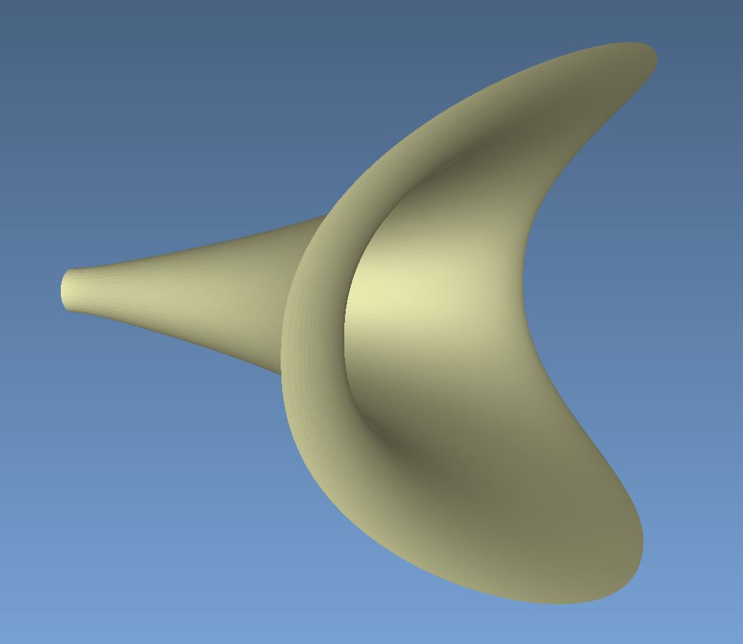
JMLC PETF 250Hz HVDiff No.1 profile

JMLC PETF 250Hz HVDiff No.1 shape
I will attach an ply file for those who would like to view the shape with a 3D viewer software: drba_jmlc_250_petf_hvdiff. The intention for different PETF parameters is to prefer the horizontal dispersion with the trade-off for the vertical dispersion and to reach also a smaller vertical foot print. The BEM results look very promising for me:
JMLC PETF 250Hz HVDiff No.1 radiation impedance
JMLC PETF 250Hz HVDiff No.1 horizontal power response

JMLC PETF 250Hz HVDiff No.1 vertical power response
JMLC PETF 250Hz HVDiff No.1 horizontal radiation polar 6dB step
JMLC PETF 250Hz HVDiff No.1 vertical radiation polar 6dB step
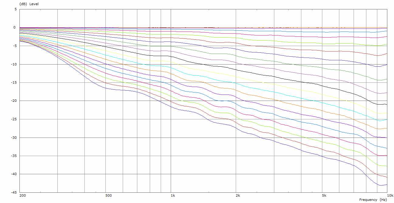
JMLC PETF 250Hz HVDiff No.1 horizontal polar (0-90, 5 degrees step)
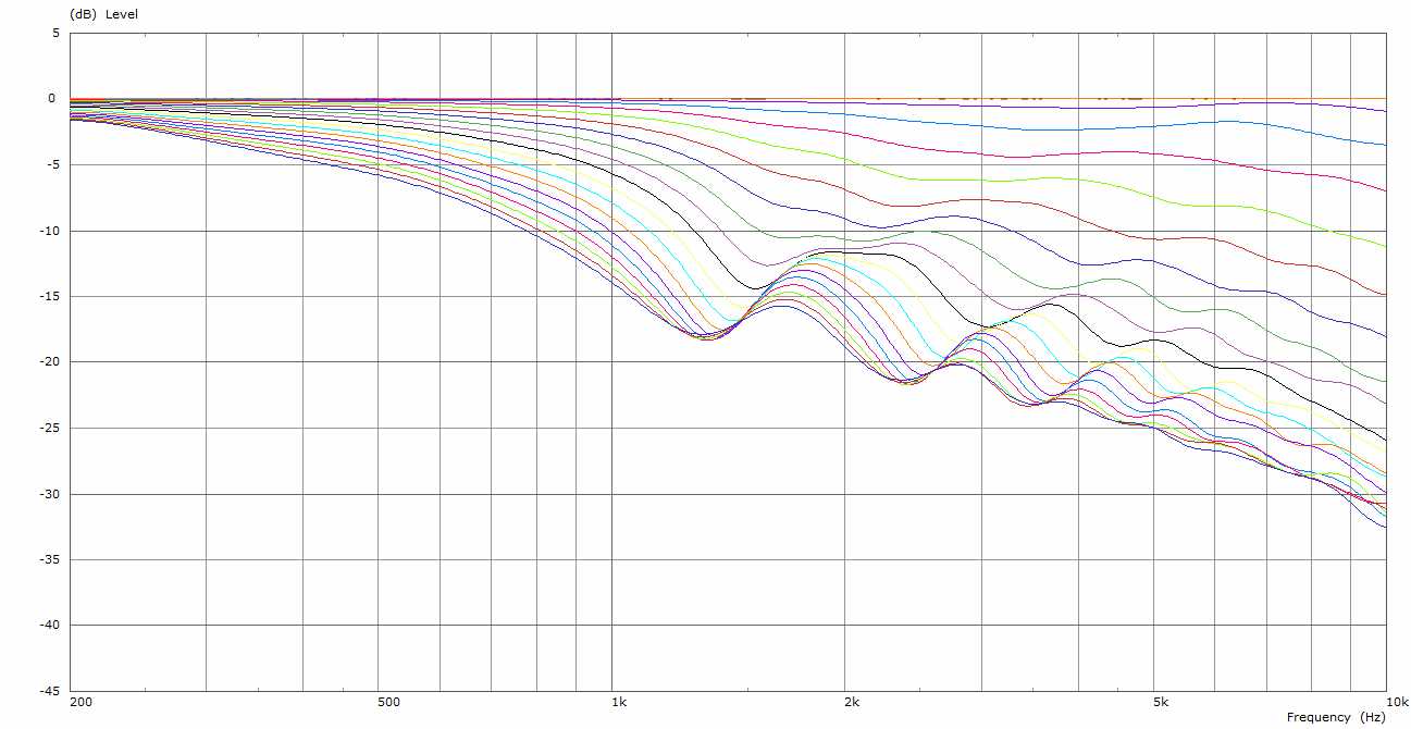
JMLC PETF 250Hz HVDiff No.1 vertical polar (0-90, 5 degrees step)
I would say mission accomplished. In the horizontal plane there is a very good directivity control with very slightly decreasing dispersion towards HF and the vertical plane remains nearly constant once the directivity control starts to lock in above 1k. There is quite good loading down to about 550Hz and fairly good loading down to 350Hz. To shift the loading down to lower frequencies is always possible with a bigger horn. The ripples especially for the vertical radiation polar are to a high degree model related because of the abrupt termination. Even a small round-over added at the edges improve the vertical figures significantly. The vertical properties could for sure be improved by making the profile wider but this was not intended here. Looking at the observation fields they do not show any visible anomalies from low to high frequencies:
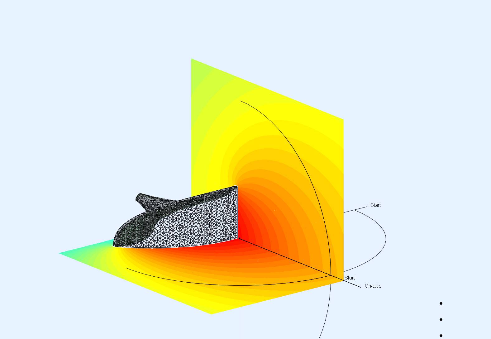
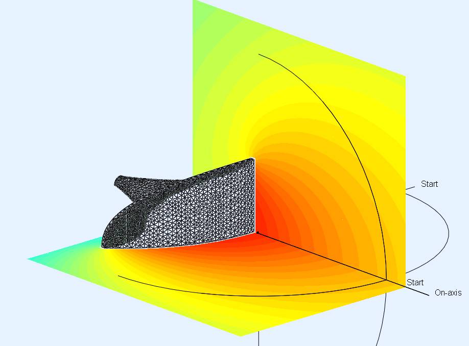
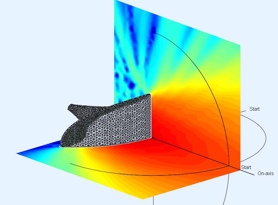
JMLC PETF 250Hz HVDiff No.1 observation field 600Hz
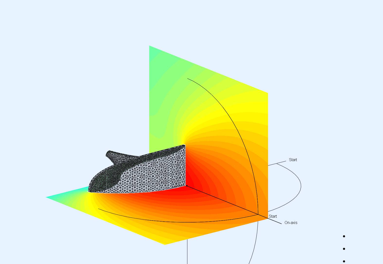
JMLC PETF 250Hz HVDiff No.1 observation field 1kHz
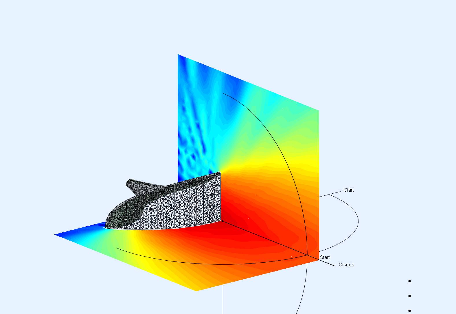
JMLC PETF 250Hz HVDiff No.1 observation field 10kHz
The second example uses different cut-off and PETF parameters and the goal was here to slightly improve the vertical dispersion:
| horizontal PETF: | T_0 = 0.5 | T_{add}=3.5 | f_{mult}=4 |
| vertical PETF: | T_0 = 0.5 | T_{add}=1.75 | f_{mult}=4 |
JMLC PETF 250Hz HVDiff No.2 profile
JMLC PETF 250Hz HVDiff No.2 shape
BEM simulation results:
JMLC PETF 250Hz HVDiff No.2 radiation impedance
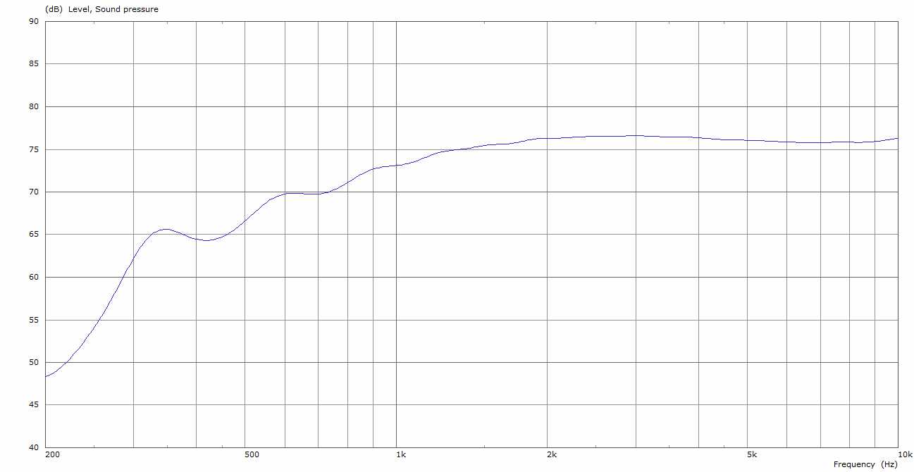
JMLC PETF 250Hz HVDiff No.2 horizontal power response

JMLC PETF 250Hz HVDiff No.2 vertical power response
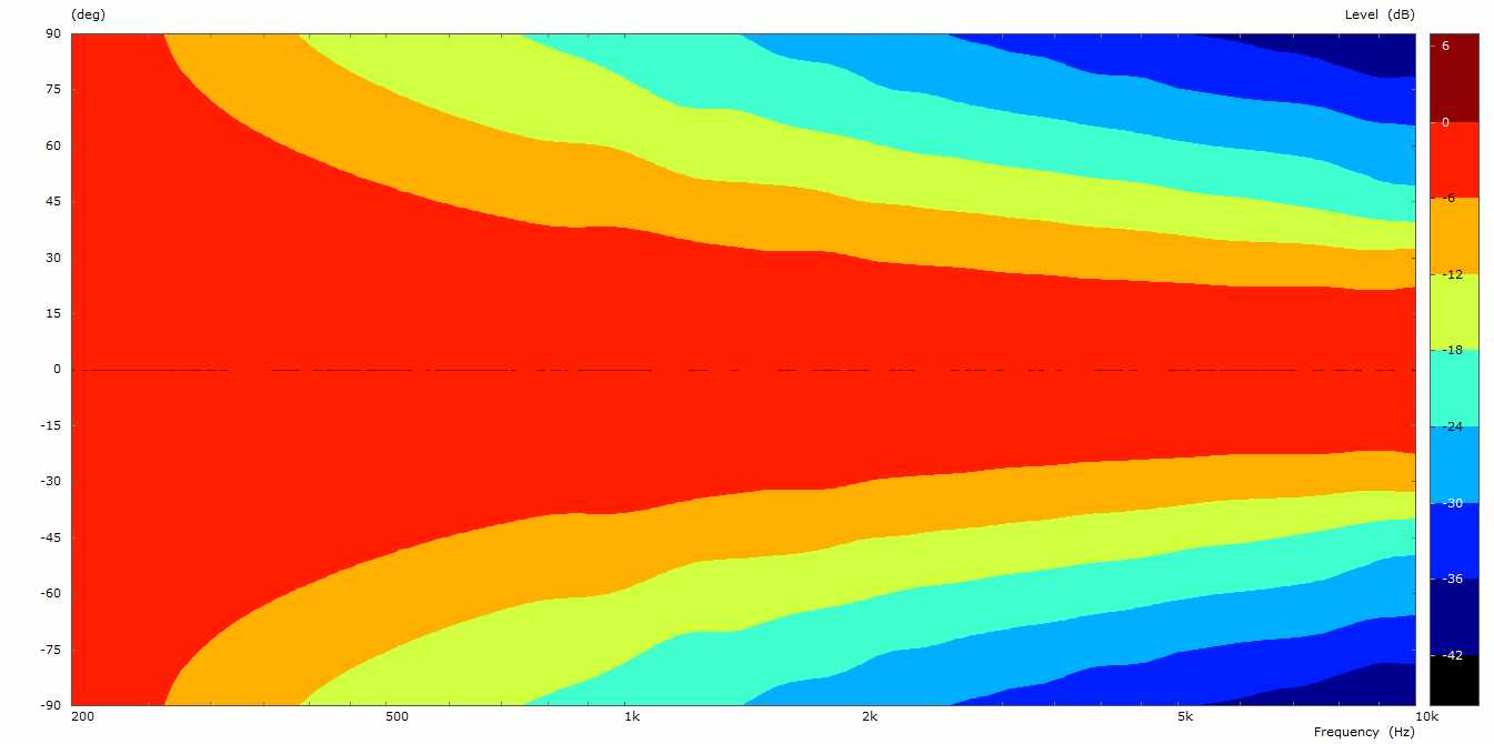
JMLC PETF 250Hz HVDiff No.2 horizontal radiation polar 6dB step

JMLC PETF 250Hz HVDiff No.2 verticalradiation polar 6dB step
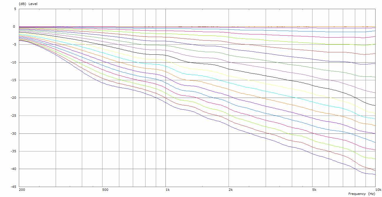
JMLC PETF 250Hz HVDiff No.2 horizontal polar (0-90, 5 degrees step)
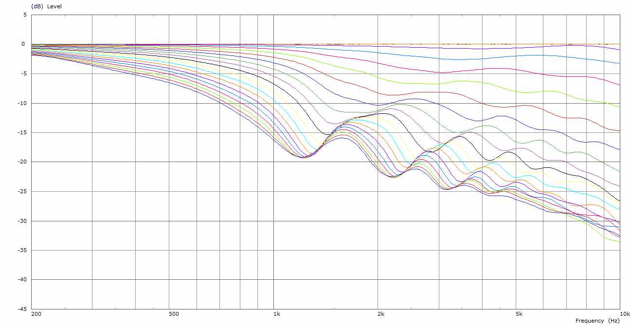
JMLC PETF 250Hz HVDiff No.2 vertical polar (0-90, 5 degrees step)
JMLC PETF 250Hz HVDiff No.2 observation field 600Hz

JMLC PETF 250Hz HVDiff No.2 observation field 1kHz
JMLC PETF 250Hz HVDiff No.2 observation field 10kHz
Again a very good performance but the improvement with respect to vertical control is not very big because of the vertical diameters of both versions are comparable and the diameter counts as bigger is better.
To summarize the results I would say that the PETF transformed horns show a great performance but they of course do not load as low as the original JMLC horns but have much better directivity control and a more even angular dispersion behaviour without midrange banding.
Is there something to compare with? Maybe yes as some longer time ago Don and me we were interested in the JMLC Iwata horn performance and were able to prepare a BEM model for a 300Hz version:
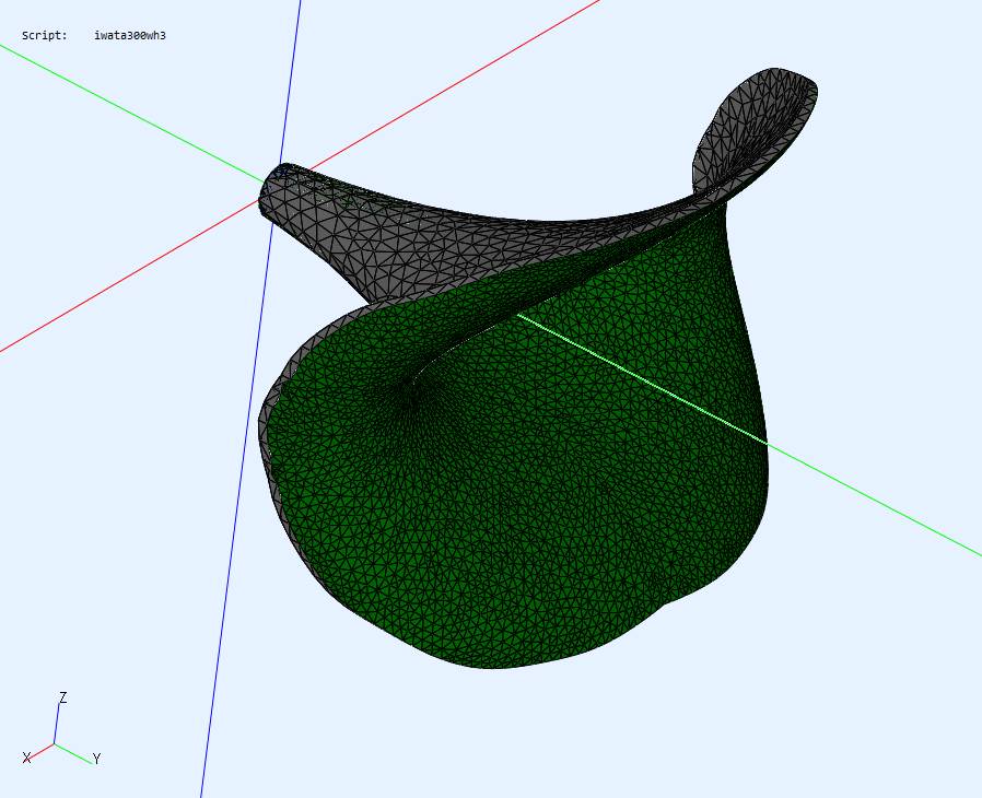
JMLC Iwata 300Hz
What is remarkable that it loads nearly perfectly down to about 300Hz. This was one of the main design goals.
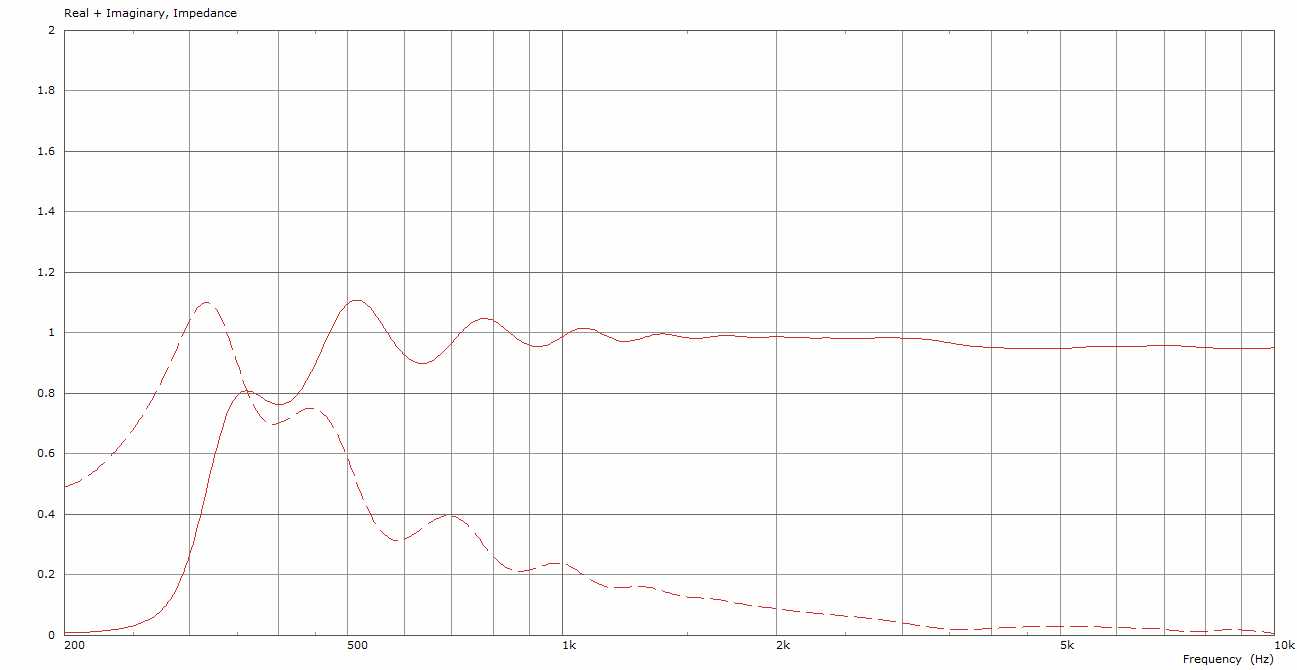
JMLC Iwata 300Hz radiation impedance
On the other side below 300Hz it has a very steep lost of loading. The main drawback is for me that the radiation is strongly angular dependent. Especially the horizontal plane show a pronounced narrowing towards higher frequencies:
JMLC Iwata 300Hz horizontal radiation polar
JMLC Iwata 300Hz vertical radiation polar
JMLC Iwata 300Hz horizontal polar (0-90, 5 degrees step)

JMLC Iwata 300Hz vertical polar (0-90, 5 degrees step)
Besides the excellent horn loading this horn is a quite beamy device and show also some midrange issues. Everyone should decide for themselves what their design objectives are, because all horns designs have tradeoffs. This technical discussion should provide some insight into those tradeoffs between loading and directivity.